Choose a positive displacement pump when the duty benefits from flow tied mainly to speed or cycle rate, particularly with viscous liquids or capacity-sensitive dosing. Choose a centrifugal pump when flow may vary with system head and the fluid and operating range suit rotodynamic pumping. Neither rule is sufficient until you define every duty point, fluid condition, suction constraint, pressure limit, and control response.
How the pumping mechanisms change system behavior
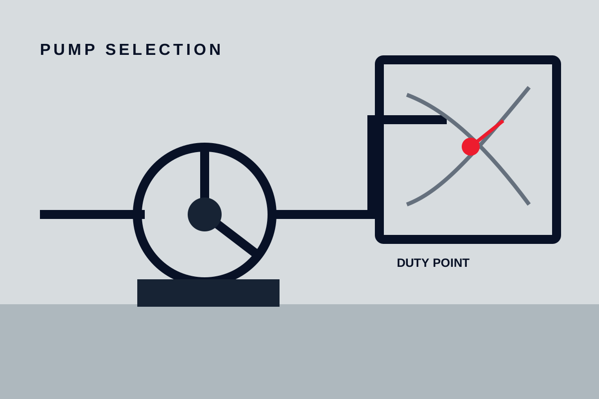
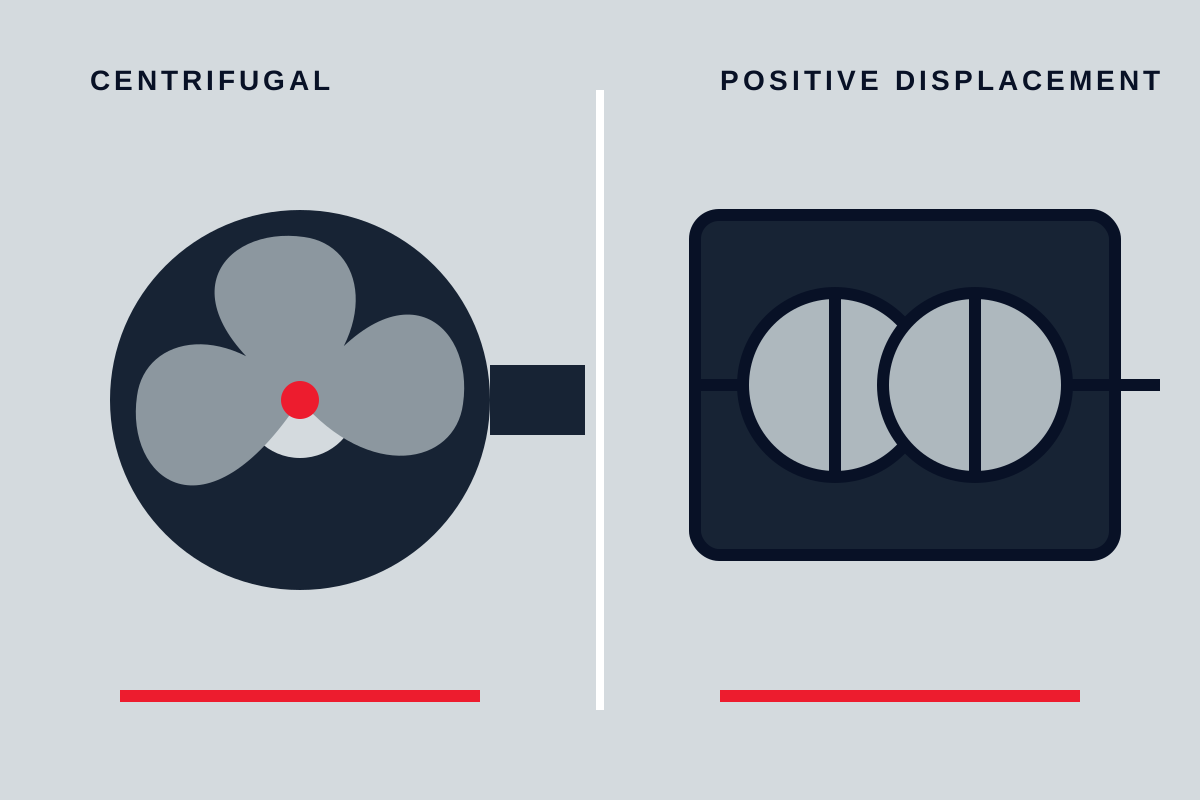
A centrifugal pump uses an impeller to add velocity to the liquid and a volute or diffuser to convert part of that velocity into pressure. Its operating flow is determined by the intersection of the pump curve and the system curve. If system resistance rises, the operating point generally moves toward lower flow and higher developed head on the same speed-and-impeller curve.
A positive displacement pump traps and moves discrete volumes of liquid. Its theoretical capacity is related primarily to displacement and shaft speed or cycle rate. Actual delivered flow is lower than theoretical displacement because of internal leakage, commonly called slip, as well as compressibility, valve behavior, wear, and other design-specific effects. Reciprocating flow may also vary substantially during each cycle even when its time-averaged capacity is stable.
This mechanism-level difference produces a useful first comparison:
| Decision variable | Centrifugal pump tendency | Positive displacement pump tendency |
|---|---|---|
| Change in system resistance | Flow changes along the pump curve | Pressure changes more than average flow, until slip or a limit intervenes |
| Capacity adjustment | Throttling, speed control, impeller selection, recirculation, or parallel pumps | Speed control, stroke adjustment on applicable designs, or bypass |
| Blocked discharge | May reach shutoff head, subject to pump and system limits | Can continue displacing liquid and raise pressure rapidly |
| Viscosity increase | Can reduce capacity and head while increasing losses and absorbed power | May reduce slip but increase inlet losses, torque, and mechanical loading |
| Flow character | Usually continuous, but not free from pressure or hydraulic fluctuations | Rotary designs vary; reciprocating designs commonly produce periodic flow |
These are family-level tendencies, not model ratings. Gear, screw, lobe, progressive-cavity, diaphragm, peristaltic, piston, and plunger pumps do not have interchangeable operating limits. Centrifugal pumps also differ by impeller geometry, staging, casing design, speed, and installation arrangement.
A manufacturer comparison from Amarinth likewise illustrates that changes in head, flow, and fluid properties affect the two families differently. Use such comparisons to identify questions, then use curves and limits for the exact offered configuration.
Define the complete flow and pressure envelope
Do not select a pump from one nominal flow and discharge pressure. Record minimum, normal, and maximum operating cases, including startup, shutdown, cleaning, line changeover, downstream closure, bypass operation, and credible changes in tank level or valve position.
For each case, collect:
- Required volumetric or mass flow, with units and allowable tolerance
- Suction-vessel pressure and minimum liquid level
- Suction and discharge pipe sizes, lengths, elevations, fittings, and valve states
- Suction and discharge pressures at defined reference points
- Static elevation difference and calculated friction losses
- Operating temperature, density, viscosity, and vapor pressure
- Continuous or intermittent operating duration and expected starts
- Maximum allowable working pressure of every exposed component
- Available motor power, starting capability, and utility limits
- Required turndown and control response
Pressure and head are related but are not interchangeable without density. For an incompressible liquid, the pressure corresponding to liquid head can be expressed as:
Δp = ρgH
where Δp is differential pressure, ρ is liquid density, g is gravitational acceleration, and H is head. State density at the relevant temperature whenever converting between pressure and head.
Develop a system curve for each meaningful centrifugal-pump case. The curve should account for static head and resistance that changes approximately with flow squared where conventional turbulent-flow assumptions apply. Systems with control valves, filters that load over time, variable vessel pressure, parallel flow paths, or non-Newtonian fluids may need more detailed treatment.
For a positive displacement pump, establish the differential-pressure envelope instead. Include the highest credible discharge pressure and lowest credible suction pressure, not only the normal gauge readings. Check shaft torque and driver capacity at maximum differential pressure, maximum viscosity, startup temperature, and other credible high-load combinations.
Use fluid properties to narrow the pump design
Viscosity is important, but it should not be used as a single universal cutoff between pump families. Obtain dynamic viscosity over the full temperature and composition range. A liquid that is readily pumpable at normal temperature may impose severe suction losses or starting torque after cooling.
Increasing viscosity usually raises piping resistance. In centrifugal service it can also change capacity, head, efficiency, and absorbed power relative to water-based curves. Apply only correction methods appropriate to the pump and fluid behavior. In positive displacement service, higher viscosity may reduce internal slip while increasing inlet losses and required torque. Excessive speed can prevent a chamber from filling properly even when the discharge pressure appears acceptable.
Screen the fluid for additional variables separately:
- Solids: Record concentration, particle-size distribution, hardness, shape, settling behavior, and whether particle damage is acceptable. A pump described as capable of handling solids may still have restrictive clearances, valves, hoses, or seals.
- Entrained or dissolved gas: Establish expected gas fraction and whether it changes during pressure reduction. Gas can affect capacity, priming, cooling, compressibility, and control stability.
- Shear sensitivity: Define an acceptable process outcome rather than relying on labels such as “low shear.” Pump speed, clearances, recirculation, valves, and the number of passes can all matter.
- Abrasiveness: Review wetted surfaces, bearings exposed to product, elastomers, valves, and clearances. Abrasion can change both service life and positive displacement slip.
- Crystallization or solidification: Identify temperatures, residence times, and shutdown conditions that may create deposits or lock the rotating element.
- Lubricity: Some designs depend on the pumped liquid to lubricate internal contact or sealing surfaces. Verify the requirement with the manufacturer.
- Compatibility and containment: Check metals, elastomers, hoses, diaphragms, seals, gaskets, and lubricants against the actual composition and temperature. Toxic, corrosive, sterile, or leakage-sensitive service may determine the containment arrangement before hydraulic selection.
- Cleanability: For hygienic or contamination-sensitive duties, define drainability, cleaning method, allowable residual volume, surface requirements, and whether the pump must be cleaned in place.
If rheology, solids behavior, or compatibility remains uncertain, arrange representative sample evaluation with an agreed method and acceptance criteria. Treat the result as applicable only to the tested fluid, temperature, pump configuration, and operating conditions.
Compare flow control and overpressure response
Centrifugal pump flow can often be adjusted by throttling a discharge valve because added resistance moves the operating point along the pump curve. Whether this is acceptable depends on energy use, minimum-flow requirements, temperature rise, vibration, recirculation within the pump, and the manufacturer’s allowable operating region.
Variable-speed control changes the centrifugal pump curve and can be effective when system resistance is mainly frictional. A system dominated by static head may offer less usable turndown than a simple speed relationship suggests. Minimum speed, motor cooling, seal operation, resonance, and control-valve authority still require review.
Positive displacement capacity is commonly controlled through speed, and some reciprocating designs permit stroke adjustment. Throttling the discharge does not regulate capacity in the same manner as it does for a centrifugal pump. Instead, the restriction can raise discharge pressure while the pump continues moving liquid, subject to slip, compressibility, drive limits, or protective action.
A positive displacement installation therefore needs a documented pressure-limiting path wherever continued displacement could exceed the allowable system pressure. The analysis should cover blocked discharge, valve failure, control malfunction, and other credible scenarios. An isolated liquid volume may also require protection against thermal expansion even when the pump is stopped.
Do not select a relief device or set pressure from a generic rule. A qualified engineer must establish device type, capacity, set pressure, accumulation allowance, return destination, backpressure effects, fluid state, and applicable project or regulatory requirements. The routing must not create an unsafe suction condition, uncontrolled heating loop, hazardous release, or incompatible return to the process.
The control narrative should define:
- The controlled variable and required accuracy
- Startup and shutdown valve positions
- Minimum and maximum permitted speed or stroke
- Response to downstream closure and low suction pressure
- Minimum-flow or recirculation requirements
- High-pressure alarms and trips
- Relief or bypass routing
- Behavior after power or instrument-air failure
Check pulsation, dry running, and suction conditions
Reciprocating positive displacement pumps commonly generate periodic flow because displacement occurs in strokes. Multiple pumping elements and pulsation-control equipment may reduce fluctuations, but performance depends on speed, phasing, fluid compressibility, pipe geometry, and device sizing. A pulsation dampener should not be assumed to correct an unanalysed piping system.
Rotary positive displacement pumps can have lower pulsation than reciprocating designs, but tooth, lobe, cavity, or screw geometry can still produce pressure and flow fluctuations. Centrifugal pumps can also produce hydraulic excitation, particularly when operating outside a suitable range or with disturbed inlet flow.
Dry-run tolerance is an attribute of the exact pump arrangement, not of the broad family. Mechanical seals, product-lubricated bearings, elastomers, hoses, diaphragms, rotors, and stators may be damaged by loss of liquid, cooling, or lubrication. Obtain a written manufacturer limit stating whether dry running is permitted, for how long, at what speed, and under what temperature and pressure conditions.
For centrifugal pumps, calculate net positive suction head available, or NPSHA, for all operating cases and compare it with the manufacturer’s NPSH required data for the exact pump, speed, impeller, flow, and test basis. The project engineer must select an appropriate margin after considering uncertainty, operating range, fluid behavior, and consequences of cavitation. NPSH required should not be treated as a universal safe margin or as a fixed property of an entire pump family.
Positive displacement pumps also require adequate inlet pressure and chamber filling. Review suction-line friction, acceleration losses for reciprocating pumps, strainers, valves, fluid viscosity, vapor formation, gas release, and maximum speed. Confirm priming requirements and allowable suction conditions with the manufacturer; not every positive displacement design is self-priming under every installation condition.
Apply a duty-based selection sequence
Use the following sequence before requesting final quotations:
- List all operating cases. Include minimum, normal, maximum, startup, shutdown, bypass, and blocked-discharge scenarios.
- Characterize the fluid. State temperature-dependent viscosity, density, vapor pressure, composition, solids, gas, abrasiveness, lubricity, and material compatibility.
- Model the system. Produce centrifugal system curves or a positive displacement pressure envelope using defined valve states and liquid levels.
- Set process constraints. Define flow tolerance, allowable shear, leakage limits, sanitation requirements, noise or pulsation sensitivity, and maintenance restrictions.
- Shortlist mechanisms. Compare exact centrifugal, rotary positive displacement, and reciprocating designs rather than stopping at the family name.
- Choose a control philosophy. Evaluate throttling, variable speed, stroke adjustment, staging, parallel operation, and recirculation as applicable.
- Check operating limits. Verify suction performance, speed, torque, absorbed power, pressure rating, temperature, minimum flow, dry running, and allowable operating region.
- Design protection. Document pressure relief, trips, guarding, containment, and safe drain or return routing.
- Confirm installation constraints. Review orientation, priming, nozzle loads, pipe strain, maintenance access, foundation, supports, and instrument locations.
- Obtain model-specific confirmation. Require the supplier to state the pump size, speed, displacement or impeller, clearances, materials, seals, driver, performance basis, tolerances, and exclusions.
Centrifugal behavior is advantageous when the process can tolerate flow changing with system head, the liquid properties suit the hydraulic design, and the required operating envelope remains within the manufacturer’s acceptable region. Positive displacement behavior is advantageous when capacity must track speed or cycle rate closely, viscosity favors displacement pumping, or the required pressure response is better served by a selected PD mechanism.
Place the selection on hold if viscosity-temperature data, vapor pressure, solids characteristics, chemical compatibility, suction conditions, pressure limits, or credible operating cases are missing. Neither family can be responsibly selected from rated flow and discharge pressure alone.
Verify the quotation, installation, and acceptance test
Compare quotations at the same flow, differential pressure, fluid properties, temperature, suction condition, and control range. A supplier statement that a pump “meets duty” is incomplete unless the performance basis and offered configuration are identified.
Request the performance curve or displacement data, general arrangement drawing, nozzle information, materials list, seal or containment arrangement, driver data, speed limits, lubrication requirements, and installation instructions. Record whether published performance is based on water, calculation, correction, or a contractually agreed test fluid and method.
Before installation, isolate electrical and other energy sources, release stored pressure, drain or decontaminate hazardous fluid where required, and follow manufacturer-specific lifting and startup procedures. Check foundation or supports, shaft alignment where applicable, pipe strain, suction geometry, rotation direction, guards, relief routing, instrument locations, and maintenance clearance.
The inspection and test plan should define which documents and physical checks are required. Depending on the project, this may include material verification, pressure testing, a witnessed performance test, vibration measurements, leakage checks, or control-response testing. These are proposed verification activities, not evidence that a particular pump has already passed.
At commissioning, record agreed variables such as flow, suction pressure, discharge pressure, speed, input power or motor current, temperatures, leakage, vibration, and control response. Accept the pump only when those results meet the contractual tolerances at the defined operating conditions and all required pressure protection, guarding, isolation, and interlocks are functional.