Noise, heat, vibration, lubricant condition, and visible surface damage can indicate bearing distress, but none proves a failure mode by itself. A reliable diagnosis compares the observed pattern with load, speed, temperature, lubrication, fits, seals, alignment, contamination, maintenance history, and damage to related machine parts.
Start with the Operating Symptom, Not the Bearing Name
The first decision is whether the bearing is actually the source of the abnormal behavior and whether continued operation is safe. A rise in running temperature, unusual noise, increasing vibration, rotational-centerline displacement, lubricant leakage, or a change in lubricant condition should trigger an investigation. These are warning signs, not diagnoses. Timken lists them as indicators that a bearing or machine requires attention, but the same symptoms can result from gears, couplings, imbalance, looseness, resonance, seals, process forces, or changes in operating conditions. Timken’s bearing damage reference guide provides a useful starting point for recording these observations.
Before interpreting the symptom, collect the operating context:
- Bearing identification, arrangement, and location in the machine.
- Shaft speed, load, duty cycle, process condition, and recent changes.
- Measurement location, instrument or sensor type, measurement direction, and time of measurement.
- Running temperature and its trend, rather than a single unqualified temperature reading.
- Lubricant grade, quantity, relubrication interval, delivery method, and any recent lubricant change.
- Recent installation, alignment, seal, shaft, housing, or coupling work.
- Previous vibration, temperature, or noise readings from the same machine under comparable conditions.
A baseline matters because a value that is abnormal for one machine may be normal for another. Avoid relying on hand-feel, an unspecified sound, or a single spot measurement. If a symptom has appeared suddenly, is accelerating, or is accompanied by severe vibration, visible damage, loss of lubrication, or a rapid temperature increase, follow the machine’s safety procedure and involve a qualified maintenance or engineering resource before further operation.
Schaeffler notes that unusual operating behavior is often an early indication of rolling-bearing damage, but inspection of the bearing alone is normally insufficient to establish the cause. The mating parts, lubrication, sealing, operating conditions, and environment must also be examined. Its rolling-bearing damage guide describes this broader inspection approach.
Separate Common Bearing Failure Patterns by Observable Evidence
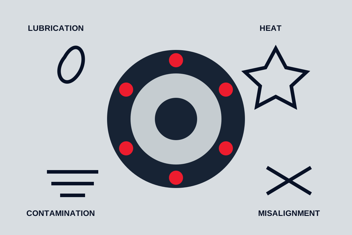
Use a consistent description before assigning a failure name. Record where the mark occurs, whether it follows the load zone, whether it is circumferential or localized, which raceway or rolling element is affected, and whether the surface is polished, smeared, indented, cracked, flaked, discolored, or corroded. Clean or polish nothing before photographs and evidence records are complete. Damage patterns can overlap, and a later event may obscure the initiating mechanism.
Fatigue, spalling, and micro-spalling
Rolling-contact fatigue can produce cracks and material loss on a raceway or rolling element. Spalling generally appears as localized areas where material has broken away from the surface. The location and shape of the damage, its progression around the bearing, load distribution, operating life, and evidence of lubrication or contamination must be considered together.
A flaked raceway does not automatically establish ordinary fatigue as the root cause. Stress concentrations, surface-origin damage, inadequate lubrication, contamination, excessive load, misalignment, or mounting effects may initiate or accelerate the damage. Use the terminology and visible-feature framework in ISO 15243:2017 to describe the observed damage, but do not treat the standard’s classification as a substitute for a root-cause investigation.
Lubrication-related damage
Insufficient, unsuitable, degraded, or poorly distributed lubricant can reduce the separating film between contacting surfaces. Possible evidence includes scoring, smearing, surface distress, discoloration, or accelerated wear. Excess lubricant can also raise churning losses and temperature, while an incompatible grease may change consistency or impair lubricant delivery.
The appearance of lubricant can support a hypothesis but rarely identifies the complete cause. Darkened grease, metallic particles, contamination, or a separated oil phase should be documented with the lubricant type, quantity, service time, temperature history, and sampling method. Check whether the lubricant reached the bearing, whether seals allowed it to escape, and whether the selected lubricant is suitable for the actual speed, load, temperature, and environment.
Contamination, indentation, and corrosion
Dirt, process material, water, condensation, or other foreign matter can damage rolling contacts. Hard particles may create dents or indentations; repeated passage of a rolling element over an indentation can generate noise and stress concentration. Moisture may contribute to corrosion, staining, or lubricant deterioration. The source may be a damaged seal, poor storage, an unclean installation, washdown, process leakage, or inadequate exclusion of the surrounding environment.
Describe the particle or mark before removing it. Note its size, distribution, location, and whether matching marks appear on rolling elements and raceways. Inspect seals, shoulders, covers, housings, lubricant paths, and nearby process equipment. A contaminated bearing may be the victim of a sealing or housekeeping problem rather than the original source of the failure.
Electrical erosion
Electrical current passing through a bearing can produce localized surface damage, often associated with fluting, pitting, or electrical discharge effects. The diagnosis requires more than a visual pattern. Examine the motor or driven equipment, grounding and bonding arrangements, variable-frequency-drive installation, insulation condition, and possible current paths. A bearing replacement without correcting the electrical path may allow the damage to recur.
The machine’s electrical safety and manufacturer requirements govern any testing. Do not infer electrical erosion solely from a grooved or discolored raceway when mechanical, lubrication, or contamination explanations remain possible.
Misalignment, mounting, and fit-related damage
Incorrect mounting, excessive or insufficient interference, shaft or housing geometry problems, skewed rings, and misalignment can concentrate load in an unintended region. Possible evidence includes localized raceway wear, edge loading, fretting, displaced material, ring cracking, or abnormal marks near a shoulder. Installation damage may also appear as dents or impact marks that correspond to handling or mounting forces.
Check shaft and housing condition, fits, shoulders, runout, alignment records, installation tools, heating methods, and assembly sequence. A bearing may be correctly manufactured yet fail prematurely because mounting force was transmitted through the wrong ring or because the mating parts did not provide the required geometry. Exact fit and clearance decisions must follow the bearing manufacturer’s data and the machine design.
Overheating and discoloration
Discoloration indicates that the component experienced a thermal or chemical change, but color alone does not identify the cause. Possible contributors include inadequate lubrication, excessive lubricant, excessive speed, overload, friction from incorrect fits, seal drag, heat conducted from adjacent equipment, or an external temperature source. Compare the discoloration across rings, rolling elements, cage components, and nearby parts, then relate it to measured temperature history and operating conditions.
Do not assign a temperature limit from color or use a generic replacement threshold. The relevant limit depends on the bearing design, material, lubricant, seals, speed, load, and manufacturer’s specified conditions.
Use Noise, Heat, and Vibration as Screening Signals
A useful symptom record includes timing, location, operating state, and trend. Record vibration at defined points and directions with the machine speed and load noted. Record temperature at a repeatable location with the instrument identified. For noise, describe whether it is tonal, intermittent, speed-related, load-related, or present during coast-down, and document how it was detected. These records are more useful than statements such as “the bearing sounded rough.”
A practical screening sequence is:
- Compare the present reading with a machine-specific baseline under a comparable speed and load.
- Check whether the symptom follows shaft speed, process load, temperature, or a change in lubrication.
- Compare the suspected bearing location with adjacent bearings, gears, couplings, seals, and structural points.
- Look for frequency or time-pattern evidence when suitable vibration equipment and competent interpretation are available.
- Confirm the finding with inspection, lubricant evidence, or controlled shutdown rather than naming a failure mode from one signal.
Vibration may indicate a bearing defect, but it can also result from imbalance, misalignment, looseness, resonance, gear damage, coupling problems, hydraulic forces, or structural conditions. Noise can be transmitted through the housing from another component. Heat can come from process conditions, seals, brakes, or adjacent equipment. SKF’s bearing failure analysis guide distinguishes inspection during operation or standstill from condition monitoring and emphasizes relating findings to the wider machine.
Do not create unsupported numerical limits for temperature, vibration, noise, clearance, or replacement intervals. Use the equipment manufacturer’s alarm values, bearing data, site standards, and an appropriate measurement method. When those limits are unavailable, report the trend and operating conditions and obtain qualified review rather than inventing a threshold.
Inspect Lubricant, Seals, Fits, and Mating Parts Before Blaming the Bearing
The bearing is part of a system. A complete inspection should include:
- Lubricant type, quantity, contamination, leakage, consistency, and delivery path.
- Seal condition, installation, contact surfaces, and evidence of water or process ingress.
- Shaft and housing fits, shoulders, fretting, scoring, cracks, runout, and deformation.
- Alignment, coupling condition, preload or axial loading, and changes in mounting arrangement.
- Load, speed, duty cycle, temperature, vibration environment, and process transients.
- Electrical grounding, insulation, and current paths where electrical erosion is plausible.
- Damage to gears, spacers, nuts, washers, cages, housings, and adjacent bearings.
The NTN-SNR failure-cause guide is useful for symptom-to-cause screening across vibration, noise, discoloration, fitting, overload, speed, temperature, lubrication, and environmental factors. Treat such tables as a way to generate and compare hypotheses, not as proof that a listed cause occurred.
Follow a Safe Inspection Sequence and Preserve Evidence
Begin with a safe operating check only when the machine can be observed without removing guards or entering a hazardous zone. Establish whether the equipment should remain in service under the site’s risk procedure. Before contact, opening, or disassembly, isolate and lock out all relevant energy sources. Account for electrical energy, stored pressure, gravity, rotation, hot surfaces, hydraulic or pneumatic accumulators, and unexpected automatic starts. Follow the machine manufacturer’s instructions and site isolation requirements.
If shutdown or removal is required, preserve evidence in this order:
- Record the machine identity, bearing position, operating state, symptom history, recent work, and last known normal condition.
- Photograph the assembly before cleaning, rotating, or removing components. Include orientation marks and the relationship to the shaft, housing, seals, and load direction.
- Record lubricant condition, leakage paths, seal position, visible contamination, and any loose or missing parts.
- Identify the removed bearing and related parts so that components from different positions cannot be mixed.
- Photograph raceways, rolling elements, cage, fits, shoulders, and mating parts before washing or polishing.
- Preserve representative lubricant or debris samples when the sampling method and chain of identification are controlled.
- Document measurements, tools, conditions, and observers; distinguish observed facts from interpretations.
Escalate to the bearing manufacturer, an independent laboratory, or a qualified engineer when the cause is uncertain, the equipment is safety-critical, the shaft or housing is damaged, electrical erosion is suspected, the bearing has severe cage or raceway damage, or the failure is recurring. Specialist analysis may require controlled cleaning, microscopy, dimensional checks, material examination, lubricant analysis, or review of machine records. Those methods should be selected for the question being investigated; they are not automatically required for every damaged bearing.
Turn the Findings into a Bounded Diagnosis and Corrective Action
A useful failure report separates four levels of certainty:
- Observed: the exact location, shape, color, debris, wear pattern, measurement, or operating change.
- Supported interpretation: the failure classification that is consistent with the evidence and the operating history.
- Competing explanations: other mechanisms that could produce a similar appearance or symptom.
- Missing evidence: records, samples, measurements, or inspections needed to distinguish those explanations.
Corrective action should follow the supported finding. It may involve restoring lubricant delivery, correcting contamination entry, repairing a seal, checking fits and alignment, reviewing load and speed, correcting an electrical current path, or inspecting related components. Replacing the bearing alone may restore operation temporarily while leaving the initiating condition unchanged.
The bounded rule is simple: identify a bearing failure type only when the surface pattern and operating evidence are consistent and reasonable alternatives have been considered. If the evidence is incomplete, report the leading hypotheses and the next verification step rather than presenting a single cause as confirmed.
Frequently Asked Questions
Can a bearing be diagnosed from noise alone?
No. Noise can justify investigation, but it may originate from a bearing, gear, coupling, seal, looseness, resonance, or process force. Correlate the sound with operating speed, load, location, vibration, temperature, and inspection evidence.
What does bearing discoloration indicate?
Discoloration indicates that the surface experienced a thermal or chemical change. Possible causes include lubrication problems, excessive speed or load, incorrect fits, seal friction, contamination, or external heat. The color must be interpreted with operating history and inspection of the complete assembly.
How can you distinguish lubrication damage from contamination damage?
Look for the combined pattern: surface appearance, particle or moisture evidence, lubricant condition, seal integrity, lubricant quantity and grade, and the machine’s environment. Lubrication-related distress and contamination damage can overlap, so a visual mark alone is not conclusive.
When should a damaged bearing be sent for specialist failure analysis?
Escalate when the equipment is safety-critical, the failure is recurring, damage is severe or ambiguous, shaft or housing damage is present, electrical erosion is possible, or the corrective action would be costly or consequential. Preserve the component and records before cleaning or disposal.