

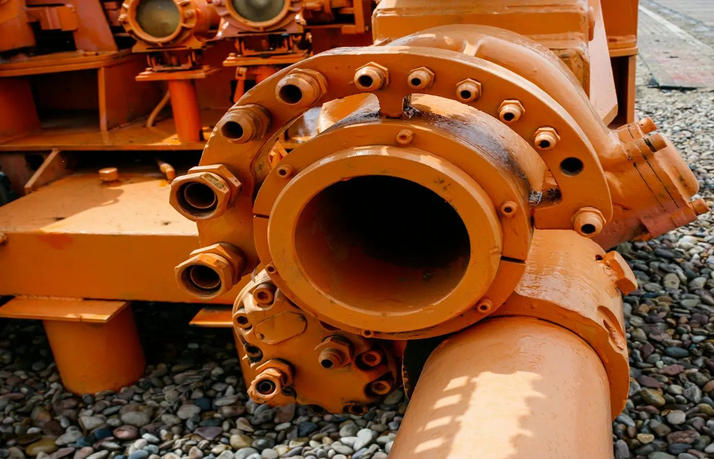
Abrasive slurry pump selection starts with the slurry and the complete piping duty, not with a nominal flow rate alone. A centrifugal slurry pump is often an appropriate starting point for continuous slurry transport, but only when the proposed pump can pass the solids, produce the required corrected head, tolerate expected wear, and remain serviceable in the installed layout. Settling solids, high viscosity, oversized particles, intermittent feed, or low-flow high-pressure duties can require a different pump arrangement or changes to the process system.
Define the slurry before selecting a pump
An abrasive slurry is more than liquid containing solids. The solids can alter hydraulic losses, reduce pump performance relative to clean water, accelerate wear, settle in pipework, and complicate shaft sealing. Obtain a representative sample and define the process conditions at the pump inlet rather than relying on a generic description such as “sand slurry” or “mineral slurry.”
The pump supplier or application engineer should receive, at minimum:
- Solids concentration by mass and, where possible, by volume
- Particle-size distribution, not only nominal particle size
- Maximum particle size and the likely presence of occasional oversize material
- Solids density or specific gravity
- Particle hardness, shape, and angularity
- Carrier-liquid density, viscosity, temperature, and chemical composition
- Corrosive constituents, pH where relevant, and any dissolved chemicals
- Whether particles settle, segregate, agglomerate, or form deposits during shutdown
- Normal, minimum, maximum, and upset operating conditions
This information distinguishes a fluid with incidental fines from a dense, abrasive transport duty. Particle shape matters because sharp, angular particles can produce different wear mechanisms from rounded particles. Settling behavior matters because a slurry that appears homogeneous in an agitated tank may separate rapidly in a suction line, pump casing, or discharge pipeline after a stoppage.
Wanner’s abrasive-duty guidance similarly identifies concentration, particle size, settling tendency, clumping tendency, and particle shape as inputs that must be assessed before deciding whether a pump arrangement is suitable. These data should come from a defined sampling method and date, particularly where feed material changes by batch, ore body, supplier, or season.
Calculate flow, head, and pipe velocity for the actual slurry
Start with the required solids throughput and process flow requirement, then calculate the system duty at the pump. The duty point includes static elevation, discharge pressure, friction losses in straight pipe, fittings, valves, bends, strainers where used, and losses across downstream equipment. It must cover normal operation as well as credible minimum, maximum, start-up, and upset cases.
Flow and head are the minimum inputs for an initial pump selection, but they are not sufficient for abrasive slurry service. Metso notes that published pump curves are generally based on clean water and that slurry and system data are needed to generate an adjusted slurry-duty recommendation. Do not treat a clean-water curve as proof that a pump will achieve the same head, power draw, or operating point with the actual slurry.
For each operating case, document:
- Required slurry flow rate.
- Static suction and discharge elevations.
- Pipeline internal diameter, material, route, fittings, and total equivalent length.
- Required discharge pressure or downstream equipment pressure.
- Suction vessel level range and available suction conditions.
- Expected solids behavior at the proposed pipe velocity.
- The supplier’s slurry correction method, selected speed, impeller diameter, and resulting curve.
Pipe velocity requires application-specific review. If it is too low for the particular particle distribution and concentration, solids may settle and progressively obstruct the line. If it is unnecessarily high, friction losses, power demand, and erosion can rise. There is no universal slurry transport velocity that can be inserted safely into every design; use the slurry characterization, pipeline geometry, and the selected manufacturer’s hydraulic method.
The proposed pump should also have an adequate suction arrangement for the real feed condition. Review suction pipe diameter, line length, high points, air ingress risk, tank geometry, liquid level, and whether solids can accumulate at the inlet. A pump cannot compensate reliably for a suction pipe that draws air, receives settled solids, or intermittently starves.
Choose a centrifugal slurry pump when the hydraulic design matches the duty
A purpose-designed centrifugal slurry pump is commonly used where slurry flows continuously, particles can pass through the wetted passages, and the required flow and head fall within the manufacturer’s stated slurry-duty envelope. Its suitability depends on the exact pump geometry, rotational speed, impeller diameter, passage dimensions, materials, seal arrangement, and operating point.
The Metso Slurry Pump Handbook explains that particle size and shape, slurry concentration, and pipeline design constrain practical slurry transport. Treat broad industry ranges as context rather than as a permissible limit for a particular pump model. The supplier should confirm allowable solids size, operating range, speed range, and duty correction for the proposed configuration.
Compare the main centrifugal-pump choices against the installation and process duty:
- Horizontal slurry pumps can offer accessible bearings, seals, and wet-end components where floor area and lifting access are available.
- Vertical slurry pumps may suit sump or tank duties where a flooded wet end is useful and the process layout supports a vertical arrangement.
- Submersible slurry pumps can be considered for certain pits, sumps, and mobile duties, subject to electrical, cooling, cable, immersion, and maintenance requirements.
- Multiple centrifugal pumps may be more practical than one large unit where operating flow varies widely, redundancy is required, or a single pump would operate too far from its intended range.
Within a chosen family, passage geometry is a central decision. A larger passage may reduce blockage risk for coarse particles but can change hydraulic efficiency and wear distribution. Higher speed can allow a smaller hydraulic unit to generate head, but it may also increase particle velocity at wear surfaces. Neither approach is universally preferable.
Ask the supplier for the exact pump curve, corrected slurry curve, recommended operating range, impeller diameter, speed, absorbed power, and motor margin for every stated duty point. Confirm that the selected operation is not based on an assumed future condition while the pump will spend most of its time at a materially different flow.
Match wetted materials and seal arrangements to the wear mechanism
Material selection is a combined abrasion, corrosion, impact, temperature, and manufacturability decision. The impeller, casing or liner, throatbush, suction liner, discharge liner, and seal-area components may each experience different exposure. A single material label is not enough to establish suitability.
The Flygt Slurry Handbook describes how slurry-pump wear varies with particle velocity, concentration, and impact angle, and identifies the impeller, pump housing, and discharge connection as important wear locations. This is why operating conditions can be as consequential as the nominal wet-end material.
Request the manufacturer’s material recommendation for the exact slurry chemistry, temperature, particle characteristics, and duty. Do not assume that a hard alloy, elastomer liner, polyurethane component, or stainless material is automatically suitable. A material that resists abrasion under one particle size and liquid chemistry can be unsuitable where corrosion, temperature, impact loading, swelling, or chemical attack dominate.
Seal selection also requires a defined containment and utility review. Possible arrangements may include packed glands with flush water, mechanical seals, expeller-assisted arrangements, or seal-less designs. Their suitability depends on seal-chamber pressure, slurry solids behavior, dry-running exposure, temperature, utility-water quality and availability, drain routing, and site leakage-control requirements.
Before approving a seal plan, verify:
- Whether seal or gland flush water is required, including pressure, flow, cleanliness, and continuity requirements
- The consequence of lost flush water or temporary loss of feed
- The route for leakage, drains, and containment
- Compatibility of seal elastomers and faces with process chemistry and temperature
- Required instruments or alarms for seal support systems
- Site procedures for responding to leakage without exposing personnel to pressure, chemicals, or rotating equipment
Design for wear inspection and planned maintenance
Wear is expected in abrasive service; the selection decision is how predictably the pump can tolerate, detect, and repair it. Do not accept an estimated wear life as a general property of a pump family. Actual life depends on the slurry, duty point, speed, material selection, operating history, and upset conditions.
Review the maintenance layout before issuing a purchase order. Confirm clearances for removing the rotating assembly, casing, liners, seal components, motor, or drive as applicable. Check lifting points, lift capacity, removal paths, isolation-valve access, drainage, and whether the arrangement permits safe work without disturbing major adjacent piping.
The maintenance plan should identify baseline readings and inspection triggers. Depending on the installation, useful condition indicators can include suction and discharge pressure, flow, power, vibration, bearing temperature, seal condition, and visible leakage. A change in these values does not by itself diagnose a specific defect, but trends can indicate that the operating point or internal hydraulic condition has changed.
Before opening a slurry pump, isolate electrical and process energy, close and secure relevant valves, depressurize, drain, flush where required by the process, and follow the site lockout/tagout and manufacturer procedures. Abrasive or corrosive residue can remain in the casing and seal area after apparent drainage.
Specify recommended commissioning spares and operating spares separately. Commissioning spares address installation and early-service risk; operating spares should reflect expected wear components, lead time, interchangeability, and the site’s acceptable downtime. Preserve records of wear-part dimensions, run hours, duty conditions, and failure observations so later replacement intervals are based on the actual service.
Use another arrangement when centrifugal-pump limits are exceeded
A centrifugal slurry pump should be reconsidered when the process cannot keep the solids in a pumpable condition or the duty cannot remain within the proposed pump’s stated limits. Common triggers include intermittent feed that permits settling, particles larger than allowable passages, highly viscous carrier liquid, severe agglomeration, strongly shear-sensitive material, very high concentration, or a low-flow high-pressure requirement that moves the pump outside its acceptable operating range.
The response may be a different pump type, but it can also be a process or piping change. Options requiring application-specific engineering review include:
- A positive-displacement pump for a duty where pressure, viscosity, or flow control makes it more suitable
- A vertical or submersible slurry arrangement for a sump, pit, or tank application
- Parallel or series centrifugal pumps where the operating envelope or required head makes multiple units more practical
- Agitation, recirculation, hopper redesign, or improved suction geometry to prevent settling at the pump inlet
- Pipe-diameter, route, or valve changes to manage transport behavior and reduce avoidable losses
Positive-displacement pumps are not a universal answer to abrasive slurry. They introduce their own questions around relief protection, pulsation, valve wear, line pressure, and sensitivity to solids geometry. Any alternative should be selected from documented process data and the exact manufacturer’s operating limits, not from a general rule that one pump type handles all difficult slurries.
Create a pump data sheet and acceptance plan before purchase
A purchase order should convert the selection basis into verifiable requirements. Attach a pump data sheet that identifies the slurry sample or characterization method, sampling date, normal and limiting duty points, system drawing references, and the supplier’s corrected-duty calculation.
Require the quotation and technical submittal to state:
- Pump model, size, configuration, rotational speed, and impeller diameter
- Corrected slurry duty curve and clean-water curve, clearly identified as such
- Flow, head, absorbed power, efficiency where supplied, and motor rating at each agreed duty point
- Wetted-component materials and seal arrangement
- Maximum stated particle size or passage limitation for the proposed configuration
- Suction requirements and any limitations on operation, start-up, or shutdown
- Motor, drive, coupling, baseplate, guarding, and instrumentation details
- General arrangement drawing, weights, lifting requirements, and maintenance clearances
- Recommended commissioning and operating spares
- Installation, operation, and maintenance documentation
Agree acceptance testing before manufacture. If a factory test uses clean water, define the test liquid, test method, instrumentation, test points, tolerances, and required records. Clean-water testing can verify the agreed hydraulic performance under those stated conditions. It does not independently prove slurry wear life, slurry head correction, sealing performance, or reliability with the actual abrasive material.
The final selection rule is straightforward: approve a pump only when measured slurry data, corrected system duty, passage capability, wetted materials, seal plan, suction conditions, and maintenance access all align with the exact manufacturer-supported configuration. If one of those items remains unknown, treat it as an open engineering or procurement risk rather than filling the gap with a generic slurry-pump rating.
Frequently asked questions
What slurry data does a pump supplier need for abrasive slurry pump selection?
Provide solids concentration, particle-size distribution, maximum particle size, solids density, particle shape and hardness, carrier-liquid properties, temperature, chemistry, settling behavior, and normal through upset duty conditions. Include piping drawings and suction-vessel information so the supplier can assess the system rather than the pump in isolation.
Why can a clean-water pump curve not be used directly for slurry duty?
Pump curves are commonly published using clean water. Abrasive slurry can change hydraulic losses, absorbed power, and achieved head. Use the exact manufacturer’s slurry correction method and verify the calculation against the measured slurry and complete system data.
How do particle size and solids concentration affect slurry pump selection?
They influence passage requirements, settling risk, wear rate, system friction, power demand, and the likelihood of blockage. The effect also depends on particle shape, density, hardness, pipeline design, pump speed, and the carrier liquid, so neither particle size nor concentration alone establishes suitability.
When should a positive-displacement pump be considered instead of a centrifugal slurry pump?
Consider it when documented process conditions such as viscosity, required pressure, low flow, feed variability, or solids behavior make centrifugal operation unsuitable. Confirm the alternative pump’s abrasive-duty limits, pressure-relief requirements, pulsation effects, and maintenance implications with the manufacturer and process engineer.