Preventing centrifugal pump cavitation requires more than showing that available net positive suction head, or NPSHA, exceeds a catalog NPSH value. Calculate NPSHA at the worst credible duty, confirm the basis of the pump curve, inspect the suction system, and retain a margin appropriate to the pump, liquid, operating range, and reliability consequences.
Distinguish cavitation from air ingestion and mechanical faults
Cavitation occurs when local pressure in the liquid falls toward its vapor pressure, allowing vapor cavities to form. As those cavities move into a higher-pressure region and collapse, they can disturb flow, generate noise and vibration, reduce performance, and damage wetted surfaces.
Noise resembling gravel, unstable flow, fluctuating pressure, vibration, or impeller pitting can indicate cavitation, but none proves it by itself. Similar symptoms can result from:
- Air leaking into suction piping operating below atmospheric pressure
- Entrained process gas reaching the pump
- Gas pockets retained at suction-line high points
- Suction or discharge recirculation away from the preferred operating region
- A restricted strainer or partly closed suction valve
- Bearing defects, misalignment, looseness, or pipe strain
- Debris contacting the impeller or casing
- Inadequate source submergence and vortex formation
Use operating records to narrow the diagnosis. Relevant measurements include flow, pump speed, suction and discharge pressure, liquid temperature, source-vessel level or pressure, valve position, strainer differential pressure, and vibration trend. Record where noise is strongest and whether it changes consistently with flow, level, temperature, or operation of another pump.
A controlled reduction in flow or speed may help distinguish a suction-energy problem from a mechanical fault, but the change must remain within manufacturer and process limits. Internal inspection may be necessary to identify erosion, debris contact, seal damage, or mechanical wear. Isolate electrical energy, release pressure, drain the equipment, and follow site and manufacturer procedures before opening a pump.
Collect the worst-case suction and duty inputs
NPSHA is a system property, not a fixed pump specification. It changes when liquid level, source pressure, temperature, flow, pipe condition, or atmospheric pressure changes. A calculation based only on normal operation can therefore conceal risk during startup, low tank level, high production demand, or an upset.
Collect these inputs before selecting a pump or investigating an existing installation:
- Minimum credible source-vessel liquid level
- Minimum absolute pressure in a closed vessel, including vacuum operation
- Site atmospheric pressure or elevation for an open vessel
- Maximum credible liquid temperature
- Vapor pressure and density at the actual composition and temperature
- Maximum expected flow and installed pump speed
- Exact pump model, stage arrangement, impeller diameter or trim, and curve revision
- Suction-pipe internal diameter, length, material, and roughness basis
- Elevations of the liquid surface, pump datum, and pressure instruments
- Losses through entrances, fittings, reducers, valves, strainers, and other components
- A reasonable allowance for fouling or strainer loading
- Startup, shutdown, parallel-pump, and transient operating conditions
Use approved process data, vessel operating limits, current piping drawings, line lists, valve data, and measured elevations. Do not use ambient-temperature water properties for a hotter liquid or a different composition. Vapor pressure can be particularly sensitive to temperature and composition.
Mark every pressure as absolute or gauge. Vapor pressure is an absolute pressure, so mixing it directly with an unconverted gauge pressure produces an invalid result. Keep pressure-head terms in consistent units and use the density of the evaluated liquid.
Calculate NPSH available at the pump suction
NPSHA is the absolute total suction head at the specified pump datum minus the liquid’s vapor-pressure head. The precise datum convention should be checked against the pump documentation and the project calculation method.
For a source vessel with negligible surface velocity, a practical system form is:
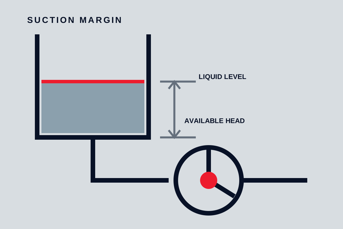
NPSHA = Hsurface,abs + Hstatic − Hloss − Hvapor
Where:
- Hsurface,abs is absolute pressure above the liquid surface divided by liquid specific weight.
- Hstatic is the vertical distance from the source liquid surface to the pump NPSH datum. It is positive when the surface is above the datum and negative for suction lift.
- Hloss is suction-system head loss at the evaluated flow.
- Hvapor is vapor pressure at the evaluated temperature divided by liquid specific weight.
For an open tank, Hsurface,abs is based on local atmospheric pressure. For a closed tank, use the minimum credible absolute vessel pressure. A vessel gauge pressure cannot replace absolute pressure without conversion; a vacuum condition reduces the surface-pressure term.
Include losses through the entire suction path, not only straight pipe. Entrance geometry, fittings, valves, reducers, strainers, temporary screens, flowmeters, and fouling can be material contributors. Calculate losses at the evaluated flow because friction generally rises strongly as flow increases.
A reusable calculation worksheet should show, without substituting assumed project values:
- Surface absolute pressure head:
p_surface,abs / (rho × g) - Static head:
z_surface − z_NPSH datum - Clean and reasonably fouled suction losses at the evaluated flow
- Vapor-pressure head:
p_vapor / (rho × g) - NPSHA for each credible operating case
- The governing, lowest NPSHA result
At minimum, run sensitivity cases for minimum level, highest temperature, maximum flow, minimum vessel pressure, and reasonably fouled suction components. Also examine combinations that can occur together rather than changing only one variable at a time.
A suction-pressure instrument can support the calculation, but its reading needs correction for pressure reference, instrument elevation, and velocity head where applicable. Confirm that the tapping location represents the pump suction and is not unduly affected by a nearby fitting or local disturbance.
The terminology for NPSHA, NPSH required, NPSH3, margin, margin ratio, cavitation, and the NPSH datum plane appears in the ANSI/HI 9.6.1 table of contents. That linked document is only a table of contents; it does not establish a numerical margin or replace the full applicable standard and manufacturer instructions.
Read the pump’s NPSH curve correctly
NPSH required is tied to a particular pump configuration and operating point. Use the curve for the exact model, impeller geometry, stage arrangement, and rotational speed being evaluated. Do not transfer a value from a similar pump size or a different trim.
Ask the manufacturer or supplier to identify:
- Whether the curve shows NPSH3 or another NPSH criterion
- The test liquid and method
- The NPSH datum used
- Applicable speed and impeller configuration
- Curve tolerances or guarantees, if any
- The recommended margin for the stated service
- The preferred and allowable operating regions
NPSH3 refers to the suction condition associated with a defined 3% loss of first-stage head during testing. It is not necessarily the point at which vapor first forms, and it does not guarantee freedom from cavitation noise, erosion, vibration, or other hydraulic effects.
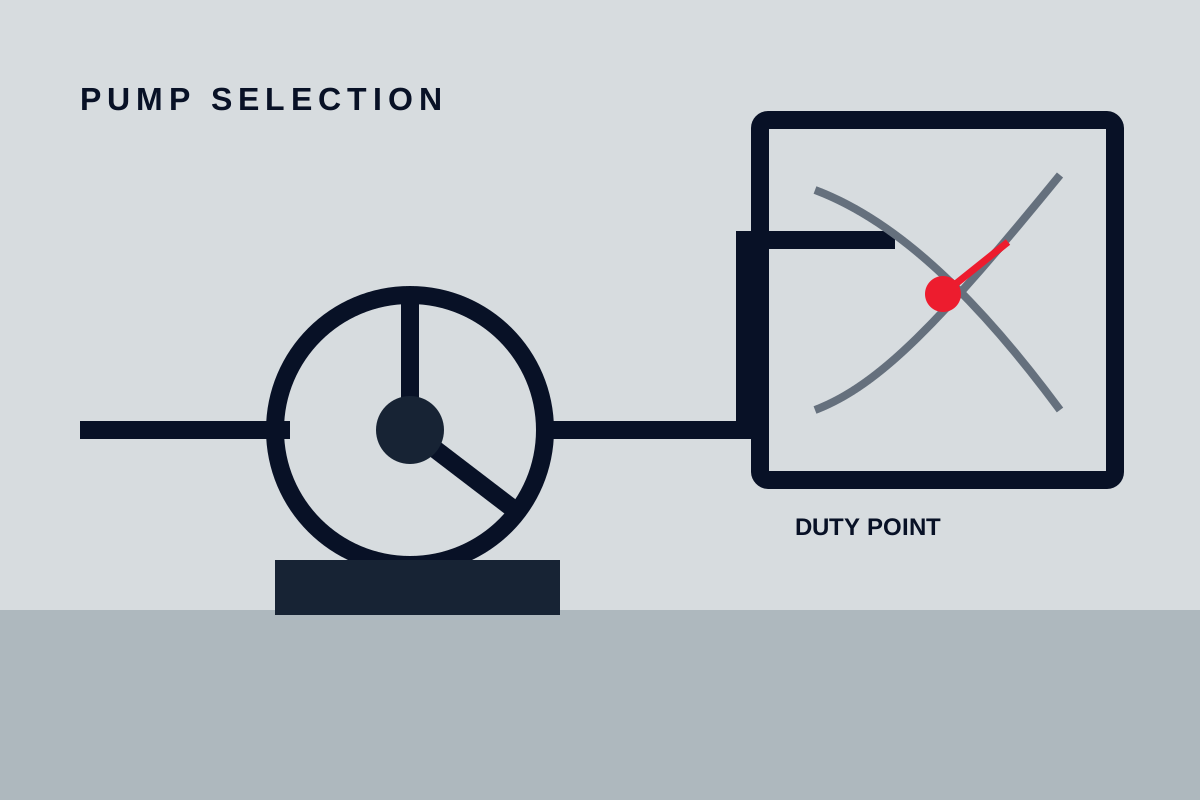
Compare NPSHA with the confirmed pump requirement across the expected operating range, not just at the best-efficiency point. Required NPSH commonly changes with flow, while system NPSHA can fall as suction losses increase. Maximum-flow operation may therefore be more limiting than the nominal duty.
Two useful ways to express margin are:
- Absolute margin = NPSHA − NPSH required
- Margin ratio = NPSHA / NPSH required
Neither supports one universal acceptance value. The required margin depends on pump design, liquid properties, operating region, uncertainty in system data, transient conditions, consequences of failure, and applicable guidance. Record both the selected criterion and its technical basis.
Inspect the suction system for losses and air entry
Calculations based on original drawings may not represent the installed system. Compare current piping isometrics with photographs, measured elevations, actual valve positions, and instrument trends.
Check for:
- A blocked or undersized strainer
- A partly closed valve or failed valve position indication
- Undersized, unnecessarily long, or heavily fouled suction piping
- Additional fittings or temporary components not included in the calculation
- High points where gas can collect
- Joints, valve stems, seals, or instrument connections that can admit air under vacuum
- Inadequate source submergence or vortexing
- An abrupt or disturbed flow approach to the pump inlet
- Unfavorable reducer installation for the actual geometry
- Interaction between pumps sharing a suction header
- Excessive nozzle loads or piping misalignment
Reducer orientation, straight-run length, suction velocity, and minimum submergence are configuration-dependent. Check the exact pump and inlet geometry against manufacturer requirements rather than applying a universal dimension.
Compare calculated suction loss with calibrated pressure measurements at defined duties. Document the pressure reference, gauge elevation, tapping location, instrument range, and units. A rising strainer differential pressure or declining suction pressure as flow increases can reveal a restriction that a static inspection misses.
Match corrective action to the limiting variable
Select the remedy from the mechanism causing the shortfall. Recalculate the operating point and NPSH margin after every proposed change.
| Limiting variable | Possible corrective action | Checks before approval |
|---|---|---|
| Excessive flow or speed | Reduce flow demand or rotational speed | Process throughput, minimum flow, motor load, control range, efficiency, and revised pump curve |
| Insufficient static head | Raise minimum source level or lower the pump | Vessel limits, structural work, flooding risk, access, and piping loads |
| Low vessel pressure | Increase source pressure where the process permits | Vessel rating, controls, relief protection, and process consequences |
| High vapor pressure | Reduce liquid temperature | Process requirements, heat-transfer capacity, viscosity, and startup conditions |
| Excessive suction loss | Clean a strainer, open or repair a valve, resize piping, or simplify the route | Fouled condition, available space, transients, and revised hydraulic calculation |
| Air entry or retained gas | Repair leaks, remove gas pockets, or revise venting and pipe profile | Vacuum conditions, seal compatibility, and safe vent destination |
| Pump requirement remains too high | Evaluate another pump, speed, impeller, inducer arrangement, or booster system | Exact curves, controls, reliability, minimum flow, and manufacturer review |
Discharge throttling can sometimes reduce cavitation risk by moving the operating point to a lower flow, which reduces suction-line losses and may reduce the pump’s NPSH requirement. It is not a universal solution: it sacrifices control-valve pressure, can reduce efficiency, and may move the pump into an unsuitable low-flow region.
A larger suction pipe can reduce friction, but it cannot correct every cause. It will not restore low vessel pressure, reduce liquid vapor pressure, eliminate an air leak, or guarantee a suitable inlet flow pattern. Larger piping may also create layout, drainage, gas-release, and cost trade-offs.
Use affinity-law estimates only for geometrically unchanged centrifugal-pump operation over a range accepted by the manufacturer. Verify speed changes against revised curves and check motor load, controls, minimum continuous flow, and the approved operating region.
Major piping changes, booster pumps, vessel pressurization, impeller modifications, or pump replacement require review by the pump manufacturer or a qualified engineer.
Verify the correction under controlled conditions
Define acceptance criteria before commissioning or troubleshooting tests. Use calibrated instruments and record their ranges, units, locations, elevations, and pressure references.
At each approved steady operating point, record:
- Flow and pump speed
- Suction and discharge pressure
- Liquid temperature
- Source level and absolute vessel pressure where applicable
- Valve positions and strainer condition
- Vibration readings at defined locations
- Relevant noise observations
- Parallel-pump or control-system status
Include normal transitions such as startup, shutdown, level change, temperature change, or parallel-pump operation where these conditions are relevant and safe. Do not deliberately hold the pump in a damaging condition to demonstrate cavitation.
Calculate the resulting NPSHA for the recorded cases and compare it with the confirmed pump curve and project-specific margin. Acceptance should require stable flow and pressure, operation within approved pump limits, the specified NPSH margin, and no unexplained adverse vibration or noise trend.
If these criteria cannot be met at the hottest liquid temperature, lowest source level, minimum source pressure, maximum approved flow, or credible suction-component condition, maintenance alone is not a sufficient closeout. Revise the duty, pump selection, source conditions, or suction-system design before accepting continuous operation.