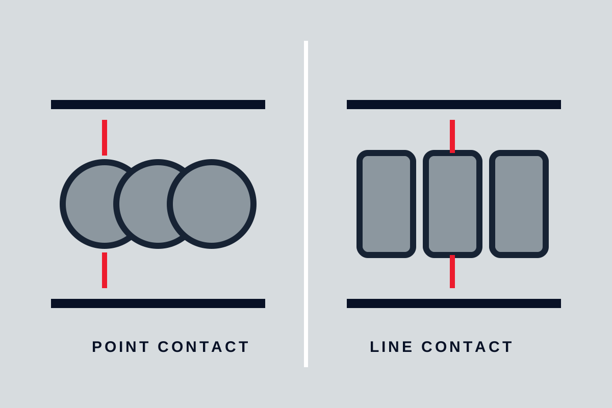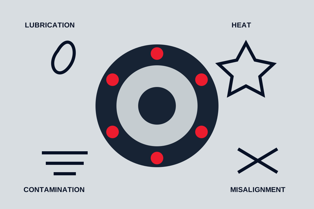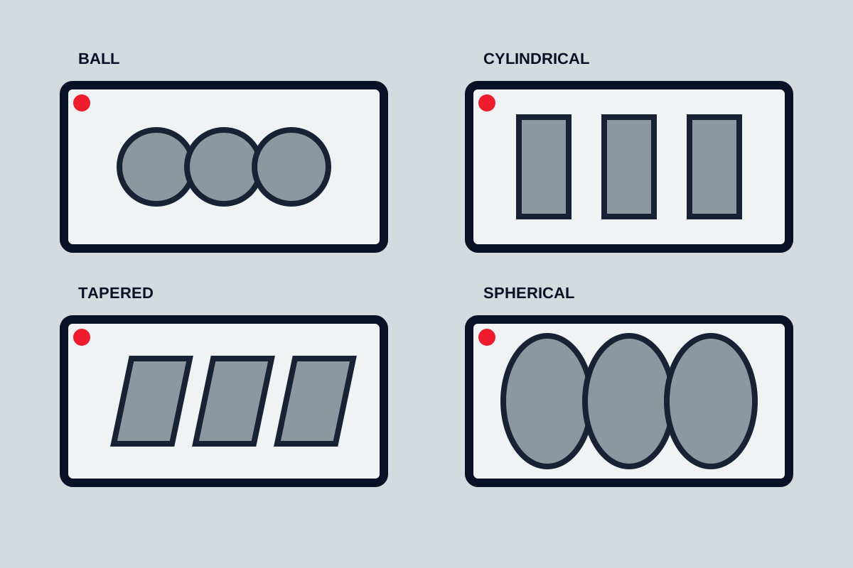
Industrial bearings support and locate rotating or sliding parts while controlling friction, stiffness, and motion. The main families—ball, roller, needle, thrust, plain, and mounted bearings—are not interchangeable labels. Each creates a different path for radial load, axial load, moment, thermal movement, and misalignment. Selection begins with the machine arrangement and operating environment, then moves to an exact bearing geometry.
Rolling-element bearings
Rolling-element bearings separate rings with balls or rollers. They offer low starting friction, predictable catalogue selection methods, and standardised mounting envelopes, but still depend on correct load, fit, clearance, lubrication, and cleanliness.
Deep-groove ball bearings are common in motors, fans, pumps, and general machinery. Their continuous raceway grooves support radial load and a useful amount of axial load in both directions. They suit high speed and are widely available in open, shielded, and sealed forms. They tolerate only limited misalignment.
Angular-contact ball bearings use an offset contact path to carry combined radial and axial load. A single bearing normally supports axial force mainly in one direction, so pairs or sets are arranged to locate a shaft, carry reversing load, or resist moment. Contact angle, preload, arrangement, and matching affect stiffness and heat.
Self-aligning ball bearings use two rows of balls and a spherical outer raceway. They accommodate angular misalignment with relatively low friction, but their load capacity and axial behaviour must be checked for the actual duty.
Cylindrical, tapered, and spherical rollers
Cylindrical roller bearings use straight rollers for high radial capacity and stiffness. Depending on which ring has guiding flanges, they may locate the shaft axially, carry limited axial load, or allow axial displacement between rings. The last function is useful where a shaft grows with temperature.
Tapered roller bearings have conical raceways and rollers. Their geometry produces combined radial and axial load capacity. They are often used in opposed arrangements so the assembly can locate the shaft in both directions. Setting endplay or preload is part of installation, not an optional adjustment after selection.
Spherical roller bearings use barrel-shaped rollers against a spherical outer raceway. They carry heavy radial load, support axial load, and accommodate angular misalignment. They are useful where shafts deflect or housings cannot remain perfectly aligned, but friction, speed, minimum load, lubrication, and heat still limit the application.
Ball and roller bearing differences are most useful when linked to one of these actual geometries.
Needle roller bearings
Needle rollers are long relative to their diameter. They provide high radial load capacity in a thin cross-section, making them valuable in transmissions, compact gear sets, pivots, and machinery with restricted radial space.
Some needle assemblies run directly on hardened shaft and housing raceways. This saves space but makes surface hardness, finish, roundness, and alignment part of the bearing specification. Drawn-cup units simplify housings but require suitable support. Machined-ring versions provide more controlled raceways.
Needle bearings do not automatically carry axial load. A separate thrust bearing or shoulder arrangement may be required. Oscillating motion, poor lubrication distribution, and edge loading need special attention.
Thrust bearings
Thrust bearings are designed primarily for axial load. Thrust ball bearings suit relatively low-friction axial support where speed and load remain within their capability. Cylindrical, needle, tapered, or spherical roller thrust bearings provide different combinations of capacity, stiffness, alignment, and speed.
Most thrust designs provide little or no radial location. A machine often needs separate radial bearings and a clear decision about which bearing controls axial position. Reversing axial load may require a double-direction arrangement.
Check how load reaches the thrust faces. Misaligned washers, flexible housings, uneven shoulders, and thermal growth can create concentrated contact even when the nominal axial load appears acceptable.
Plain bearings and bushings
Plain bearings support motion through sliding contact rather than rolling elements. They include hydrodynamic journal bearings, dry or marginally lubricated bushings, spherical plain bearings, and lined composite designs.
Hydrodynamic bearings can carry high load with very low wear once a full lubricant film develops, but start-up, shutdown, speed, clearance, viscosity, supply, and contamination are critical. Dry-running bushings use material combinations selected for low friction and controlled wear; their load-speed-temperature limits depend on the exact material and duty.
Plain bearings can suit oscillation, shock, dirty environments, large diameters, and slow movement where rolling bearings are difficult. They may also tolerate embedded debris or edge conditions differently. The trade-off is that friction, wear, lubrication, and clearance change over life and must be included in the design.
Mounted bearing units
Mounted units combine a bearing insert with a housing such as a pillow block, flange, or take-up form. They simplify installation on conveyors, fans, agricultural equipment, and general machinery. Many inserts use spherical outer surfaces to accommodate initial housing misalignment.
The unit still requires correct shaft size, locking method, load direction, speed, seal, relubrication, and support stiffness. A self-aligning housing does not correct a bent shaft, unstable structure, or excessive dynamic misalignment. Set-screw, eccentric collar, adapter sleeve, and interference locking methods affect concentricity and reversing-load suitability.
Important selection variables
Build the selection around the bearing arrangement:
| Variable | Selection implication |
|---|---|
| Radial and axial load | Determines bearing geometry, size, and arrangement |
| Speed and acceleration | Affects cage, lubrication, friction, and heat |
| Shaft location | Defines fixed, floating, paired, or thrust-bearing functions |
| Misalignment and deflection | May require self-aligning geometry or structural correction |
| Stiffness and accuracy | Influences roller choice, preload, fits, and support design |
| Temperature | Changes lubricant, clearance, fits, seals, and thermal movement |
| Contamination | Drives sealing, filtration, handling, and maintenance strategy |
| Mounting access | Affects separable designs, tools, heating, and removal method |
Dynamic and static load ratings are inputs, not complete decisions. Duty cycles, shock, minimum load, reliability target, lubricant cleanliness, and mounting quality determine whether calculated life is meaningful.
Clearance, preload, and fits
Internal clearance is measured before mounting but changes after rings are fitted and temperatures stabilise. Interference on a ring reduces internal clearance. A hotter inner ring may reduce it further. Select initial clearance to achieve the required operating condition.
Preload deliberately removes clearance to increase stiffness and running accuracy. Excessive preload creates heat and short life. It requires a controlled arrangement and assembly method, especially with angular-contact and tapered bearings.
The ring exposed to rotating load generally needs a fit that prevents creep, but the final fit depends on load, ring material, shaft and housing construction, and required axial movement. Shoulders, fillets, spacers, and locknuts must support and locate the rings without interfering with chamfers or seals.
Lubrication, sealing, and monitoring
Choose oil or grease based on speed, load, temperature, heat removal, contamination, orientation, and maintenance access. More lubricant is not automatically safer; overfilling can churn and overheat. Relubrication intervals are application-specific and should be adjusted from observed condition, not copied blindly.
Seals must balance exclusion and friction. Contact seals protect against contamination but add heat and wear. Non-contact labyrinths support speed but may need grease purge or air management in dirty service. The housing and shaft surface are part of the sealing system.
Establish baseline temperature, vibration, lubricant condition, and noise after correct commissioning. Trend changes instead of relying on a single universal alarm value. If damage occurs, preserve the evidence and follow a structured bearing failure investigation.
Final bearing selection sequence
- Map every radial, axial, moment, shock, and minimum load through the shaft and housing.
- Decide which bearing locates the shaft and where thermal displacement occurs.
- Shortlist geometry for load direction, speed, stiffness, and misalignment.
- Check rating and life across the duty cycle without ignoring contamination and lubrication.
- Select internal clearance or preload, fits, shoulders, and setting method.
- Define lubricant, delivery, seals, monitoring, mounting, and removal.
- Confirm the complete arrangement through drawings and installation instructions.
The bearing type is only one element of rotating-equipment reliability. A correctly chosen bearing can still fail quickly if the shaft, housing, lubrication, sealing, or assembly does not support the same operating assumptions.
Thrust and needle designs
Thrust bearings are arranged primarily for axial load. Needle rollers provide high radial capacity in a small cross-section but demand accurate raceways and alignment. Combined designs can support multiple load directions where packaging space is limited.
Plain and mounted bearings
Plain bearings slide rather than roll and can suit oscillation, shock, dirty environments or very high loads when lubrication and material pairing are correct. Mounted bearing units simplify installation but still require shaft fit, sealing and alignment checks.