Pump mechanical seal selection should begin with the actual conditions in the seal chamber and the consequences of leakage—not with a preferred seal type. Fluid composition, solids, vapor margin, chamber pressure, temperature, shaft speed and loss-of-lubrication scenarios determine the suitable face materials, secondary seals, arrangement and support system.
Define the fluid and seal-chamber duty first
A pump datasheet that lists only flow, differential head and motor power is not enough to select a seal. The seal supplier needs to know what reaches the seal faces during normal operation, startup, shutdown, standby, cleaning and credible upset conditions.
Collect at least the following inputs:
- Fluid identity, composition and concentration
- Trace contaminants and expected variation between batches
- Solids concentration, particle size, hardness and settling behavior
- Viscosity across the operating temperature range
- Lubricity and presence of dissolved or entrained gas
- Tendency to crystallize, polymerize, coke, cure or form deposits
- Vapor pressure at normal and maximum credible seal-chamber temperatures
- Toxicity, flammability and allowable process emissions
- Whether product leakage to atmosphere is acceptable
- Whether buffer or barrier fluid may enter the process
- Normal, minimum and maximum seal-chamber pressure and temperature
- Startup, shutdown and upset pressure and temperature
- Shaft diameter, rotational speed and direction of rotation
- Startup frequency, standby duration and expected cycling
- Cleaning, flushing, steaming or sterilization fluids and temperatures
Use the actual seal-chamber pressure rather than substituting suction or discharge pressure. Chamber pressure depends on pump geometry, operating point, balance features and any connected recirculation or flush system. Request the pump manufacturer’s sectional drawing and pressure data for the relevant pump configuration.
Where conditions vary, provide a duty table instead of one nominal value. A seal selected only for the rated operating point may encounter its most severe pressure, temperature or vapor-margin condition at minimum flow, startup or shutdown.
Match every wetted material to the complete exposure
A mechanical seal normally includes rotating and stationary faces, secondary sealing elements, springs or bellows, drive components and other wetted metal parts. These components can have different chemical and mechanical limitations.
Face selection depends on more than corrosion resistance. The face pair must support a stable lubricating film while resisting wear, distortion, thermal damage and attack by the process. Hard face combinations may be considered where abrasive particles are present, but material names alone do not establish suitability. Face grade, binder, porosity, finish, loading and the characteristics of the solids can all affect the result.
Secondary seals—often O-rings, wedges, gaskets or bellows—must remain compatible and mechanically functional over the full temperature and chemical exposure range. Swelling, hardening, loss of elasticity or excessive compression set can prevent a secondary seal from moving or sealing correctly. Cleaning chemicals can be more aggressive than the pumped product and must be included in the review.
Likewise, a generic description such as stainless steel, carbon, ceramic, silicon carbide or fluoroelastomer is incomplete. Ask for exact material grades or supplier designations. Check compatibility information at the stated concentration and temperature, including impurities and expected exposure duration.
Compatibility tables are screening tools, not final approval. They may not address mixed chemicals, cyclic exposure, mechanical loading or long-term behavior. If published information is incomplete, request a written material review from the seal supplier or define controlled compatibility testing with the exact materials and conditions identified.
Check pressure, temperature, speed and vapor margin together
Seal ratings are interdependent. A published maximum pressure cannot be treated as valid at every temperature, speed, shaft size and face combination.
Pressure creates hydraulic forces that influence face loading. Excessive closing force can increase friction and heat generation, while inadequate or unstable loading can allow excessive separation and leakage. A balanced seal reduces the effective hydraulic loading on the faces, but the allowable operating envelope still belongs to the exact design and configuration. Balanced does not mean unrestricted pressure capability.
Temperature affects the pumped fluid, secondary seals, metal components and the flatness of the faces. The temperature at the sliding interface can be higher than the measured bulk-fluid or chamber temperature because the faces generate frictional heat. Cooling and circulation therefore matter as much as the nominal process temperature.
Speed also influences heat generation and face behavior. The supplier should evaluate the combination of shaft diameter and rotational speed, not speed alone. Shaft movement, runout and vibration can further reduce the seal’s ability to maintain an appropriate face relationship.
Vapor margin requires particular attention. If local pressure at the faces falls toward the fluid’s vapor pressure, or local heating raises that vapor pressure, the lubricating film can flash. The resulting unstable liquid-and-vapor condition may increase heat, wear and leakage.
Request a pressure-temperature-speed operating envelope for the exact seal model, shaft size, balance design, face combination and secondary-seal materials. Compare it with minimum, rated and maximum pump operation as well as startup, shutdown and credible upset conditions. Conditions near a published boundary should receive written engineering review from the pump and seal manufacturers.
Control solids, deposits, flashing and dry-run exposure
Mechanical seal faces depend on a suitable interfacial fluid film. Dry running, entrained gas, flashing, abrasive particles and deposits can disrupt that film or prevent the faces from tracking correctly.
The appropriate response depends on the mechanism:
- Air trapped during startup: improve filling and venting procedures, and confirm the seal chamber can vent in the installed orientation.
- Loss of suction or low tank level: consider level, pressure or flow instrumentation with alarms or trips appropriate to the process risk.
- Loss of an external flush: monitor the property that demonstrates effective support, such as pressure, flow or temperature, and define the required control action.
- Abrasive solids: review particle size, concentration, hardness, settling and circulation paths; consider slurry-oriented seal features or a suitable clean flush.
- Crystallization or polymerization: avoid stagnant regions and identify the temperature, concentration or residence-time conditions that initiate deposition.
- Flashing at the faces: review chamber pressure, temperature, vapor pressure, circulation and heat removal rather than changing face materials alone.
A clean flush can improve the environment around the faces, but it can also dilute or contaminate the product, consume utilities and alter chamber pressure. Flush quality, pressure, temperature and flow must be specified. A connection on the gland does not prove that effective circulation will occur.
Do not assume a mechanical seal can tolerate a fixed period of dry running. Allowable exposure, if any, depends on the exact design, face materials, loading, speed, cooling and definition of the test. Obtain any dry-run limit in writing, together with its conditions. If loss of liquid is frequent or unavoidable, reconsider the pumping and sealing technology rather than treating dry running as a normal seal duty.
Compare single, dual, cartridge and alternative approaches
Seal arrangement and construction answer different questions. Arrangement concerns containment and pressure relationships; cartridge construction concerns how components are assembled and positioned.
| Approach | When it may be considered | Main points to verify |
|---|---|---|
| Single mechanical seal | Process leakage can be safely managed and the fluid provides a suitable face environment | Expected leakage path, venting, flush needs, emissions limits and drain provisions |
| Unpressurized dual arrangement | Additional containment or collection is required while the process-side seal remains the primary seal | Buffer-fluid compatibility, leakage destination, secondary-seal capability and monitoring |
| Pressurized dual arrangement | Process fluid must be prevented from reaching the atmosphere under the defined pressure relationship | Barrier pressure margin, barrier-fluid ingress, circulation, heat removal, alarms and response to pressure loss |
| Cartridge seal | Controlled assembly and installation dimensions are useful | Correct interfaces, setting-device procedure, rotation, gland orientation and axial space |
| Component seal | The pump and maintenance system are designed for field assembly and setting | Installation dimensions, cleanliness, setting accuracy and technician procedure |
| Packing | Controlled leakage and periodic adjustment are acceptable | Sleeve wear, leakage management, adjustment access and product compatibility |
| Sealless pump | Leakage consequences justify eliminating a conventional rotating shaft penetration | Secondary containment, internal bearings, heat removal, solids tolerance, dry-run limits and monitoring |
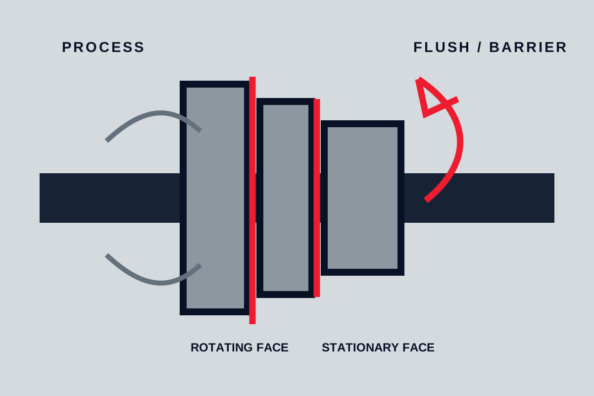
An unpressurized dual arrangement typically uses an outer seal to provide secondary containment and a buffer fluid below process pressure. A pressurized dual arrangement uses a barrier fluid maintained above process-side pressure so that leakage direction is intended to be toward the process rather than from the process to atmosphere. Neither arrangement guarantees zero leakage; the supplier must define the leakage paths, pressure relationships and monitoring criteria.
Terms such as double, dual, tandem, back-to-back and face-to-face are not always used consistently. Require an arrangement drawing that identifies both seals, the process and atmospheric sides, circulation paths, normal pressures and destinations of leakage.
Cartridge construction can reduce field setting work because the seal is supplied as an assembled unit, but it does not correct incompatible materials, inadequate circulation, excessive shaft movement, flashing or dry running. It also does not determine whether the seal is single or dual.
Where API 682 terminology is invoked, state the applicable edition and purchaser requirements in the inquiry. A secondary overview of API 682 seal arrangements explains common selection distinctions, but the applicable standard and owner specification should be reviewed directly. Guidance described as informative should not be represented as a mandatory requirement unless the purchase specification makes it one.
Specify the support system and installation conditions
The seal, gland, piping, utilities and instrumentation function as a system. Selecting the seal without defining its support conditions leaves major failure mechanisms unresolved.
Ask for drawings showing:
- Seal-chamber dimensions and connection locations
- Shaft or sleeve diameter, finish, runout and movement limits
- Rotation direction and cartridge installation length
- Available radial and axial space
- Flush, vent, drain, quench, buffer or barrier connections
- Required piping orientation and circulation direction
- Cooling requirements and utility limits
- Instrument types, ranges, alarm settings and trip basis
For dual seals, the supplier should identify the buffer or barrier fluid, operating pressure, expected temperature range, circulation method and heat-removal duty. The fluid must be compatible with the process, seal materials and consequences of ingress in either direction.
Installation and commissioning must follow the pump and seal manuals. Before work begins, isolate electrical and other energy sources, depressurize, drain and decontaminate the equipment under the site’s approved procedures. Guards must be restored before operation.
Practical pre-start checks include correct rotation, alignment, valve lineup, chamber venting, support-fluid availability and functioning instruments. Cartridge setting devices must be used and removed in the sequence specified by the manufacturer. Do not turn an installation convention into a universal procedure across different seal designs.
Turn the selection into an auditable purchase specification
A quotation should identify what is being supplied and the conditions under which the supplier considers it suitable. Include a completed seal datasheet and request the following submittals:
- Exact seal model, construction and physical arrangement
- Drawing showing leakage and circulation paths
- Bill of materials with exact face, secondary-seal and wetted-metal grades
- Stated chemical-compatibility basis and unresolved exclusions
- Rated pressure-temperature-speed envelope for the offered configuration
- Shaft, sleeve and seal-chamber interface requirements
- Support-system schematic, calculations and utility requirements
- Instrument list with alarm and trip basis
- Expected buffer, barrier or flush-fluid consumption where applicable
- Installation, storage, commissioning and maintenance instructions
- Clearly identified deviations from the inquiry or owner specification
- Proposed inspection and test procedures with acceptance criteria and record requirements
Do not accept a datasheet marked suitable without checking it against minimum, normal, maximum, transient and cleaning conditions. Any supplier qualification should be tied to the exact seal configuration rather than transferred from a different model, material combination or shaft size.
Mechanical seal selection questions
Can a mechanical seal run dry during pump startup?
Do not assume that it can. The chamber should normally be filled and vented according to the pump and seal manuals before startup. If dry exposure is credible, obtain a written limit for the exact seal design and conditions or provide controls that prevent startup without the required liquid and support services.
Is a cartridge seal always better than a component seal?
No. A cartridge seal can simplify positioning and assembly, but suitability still depends on materials, chamber duty, shaft condition, support systems and available installation space. A correctly selected and installed component seal may be appropriate where the pump and maintenance procedure are designed for it.
When does a pump need a double or dual mechanical seal?
Consider a dual arrangement when leakage consequences, emissions limits, poor process lubricity or the need for an externally controlled face environment make a single seal inadequate. The physical arrangement and pressure relationship must be selected around whether process leakage, buffer-fluid leakage or barrier-fluid ingress is acceptable.
Which pressure should be used to select a pump mechanical seal?
Use the seal-chamber pressure across the full operating range, including transient and upset conditions—not discharge pressure by default. Obtain the chamber pressure from pump data or an engineering calculation that accounts for the actual pump geometry and connected support piping.
The final acceptance criterion is an exact seal and support-system configuration with documented material compatibility, an operating envelope covering every specified duty point, defined leakage paths, verified interfaces and commissioning checks. If any of those items remains undefined, the mechanical seal selection is not complete.