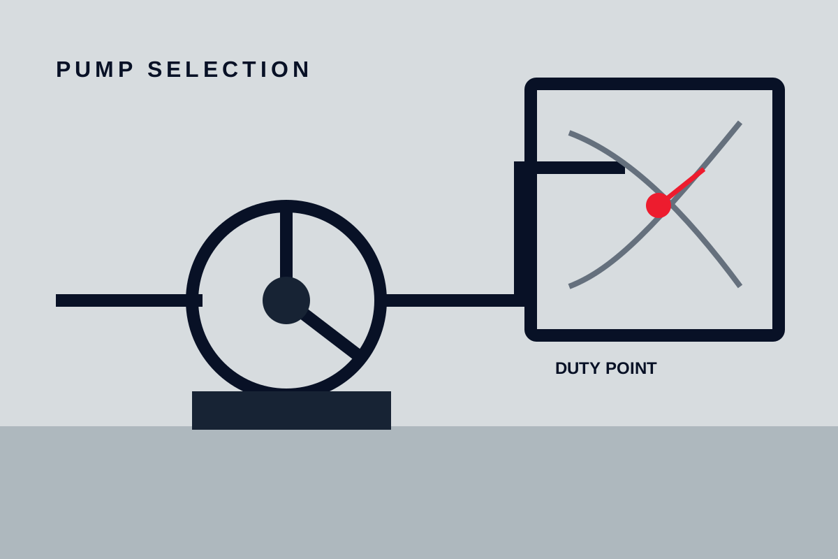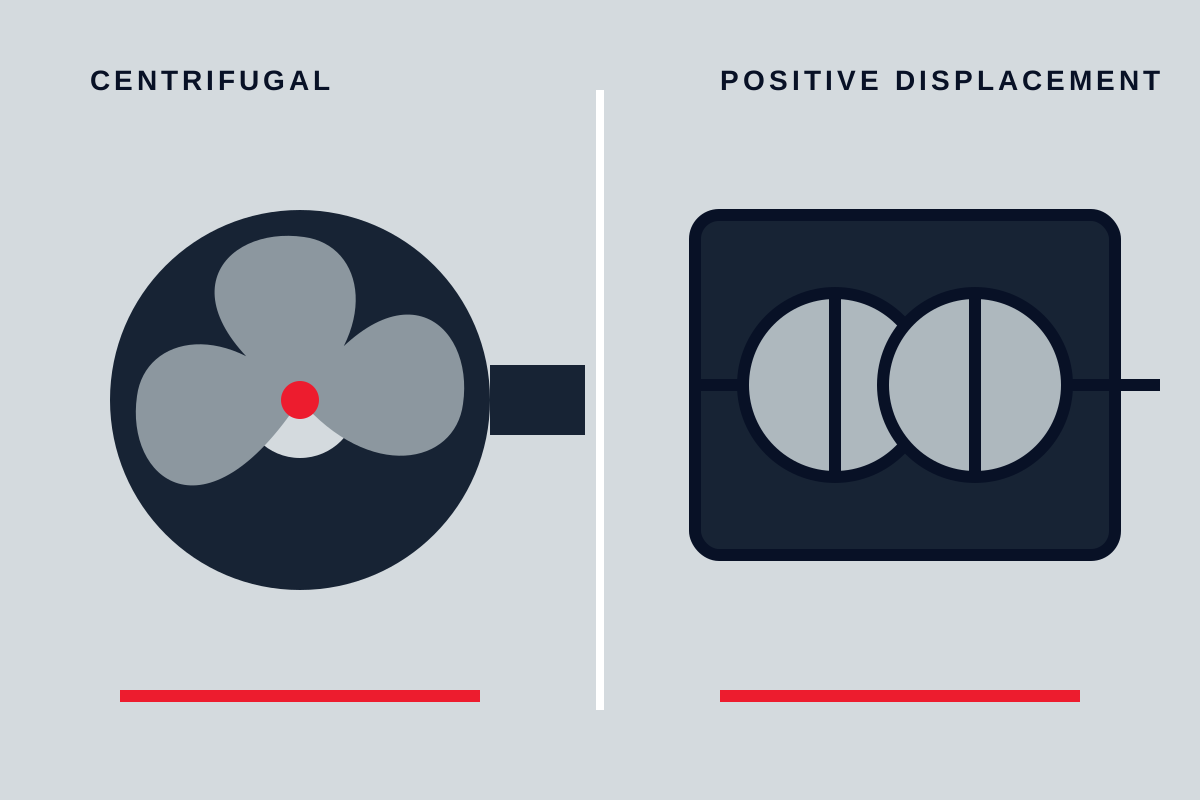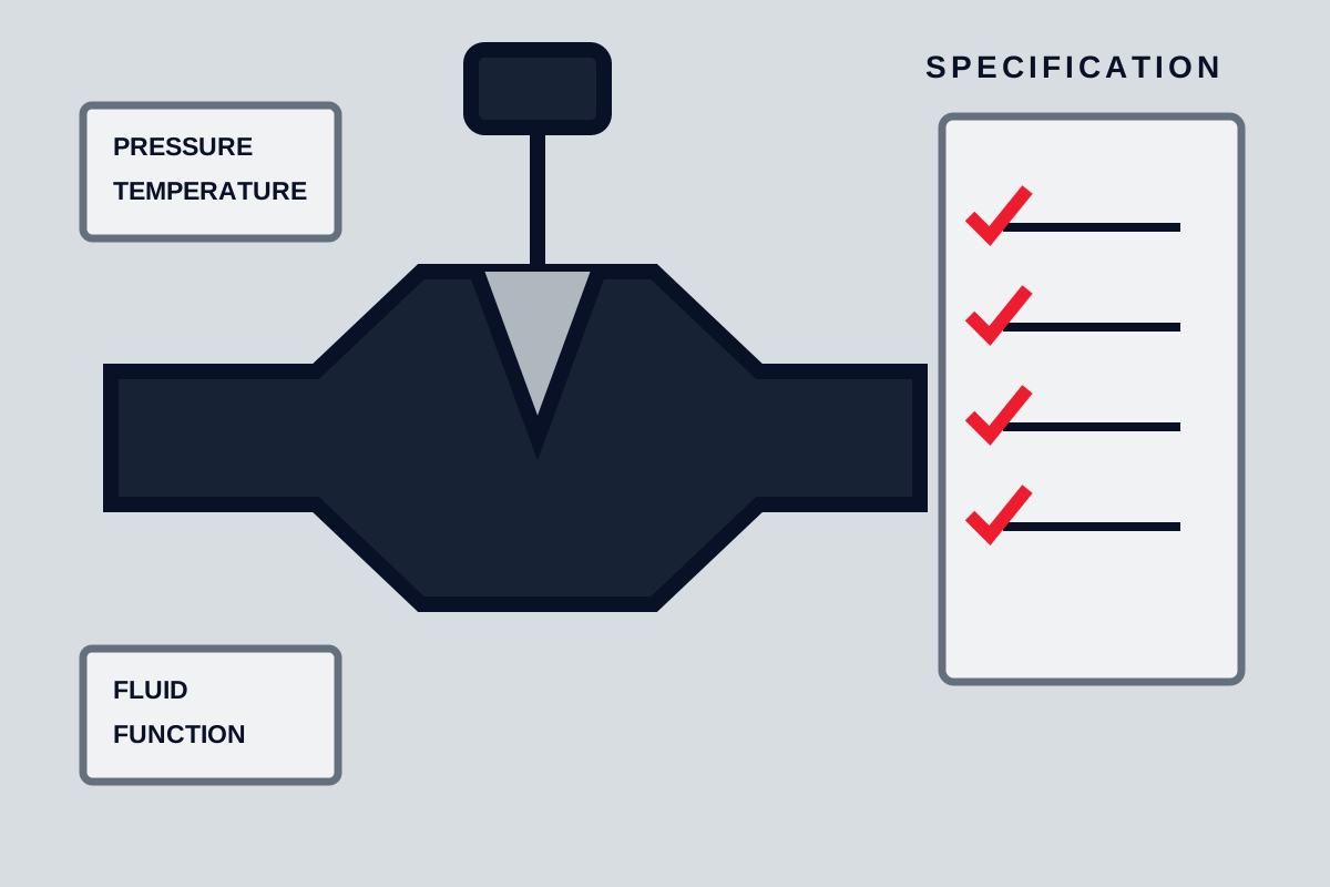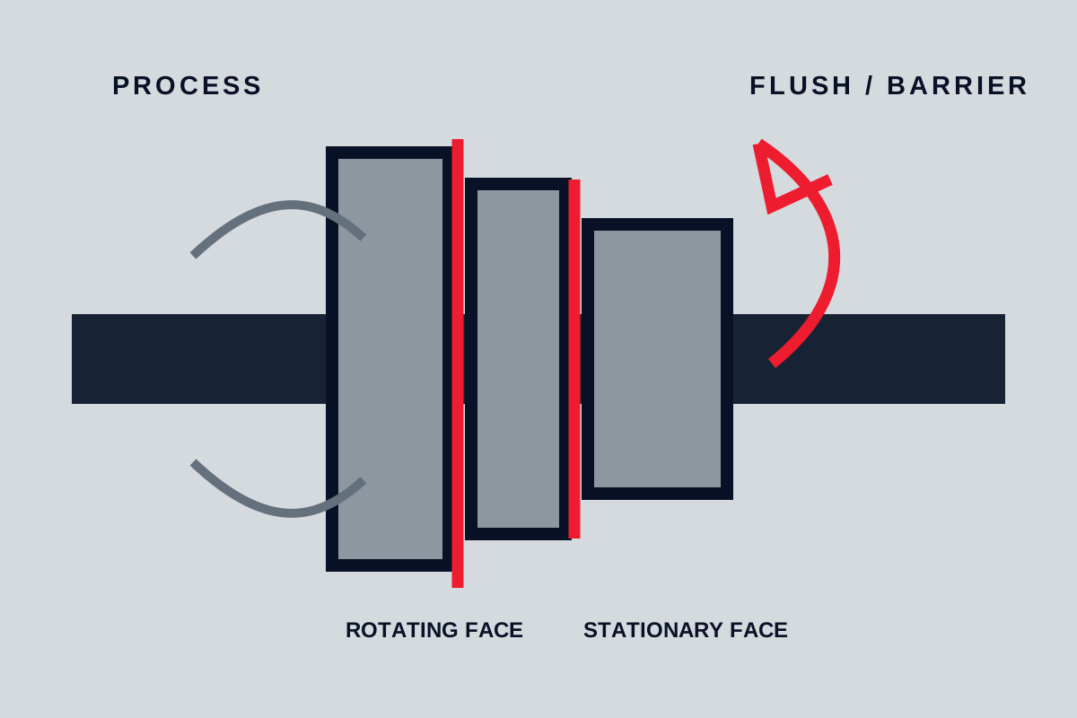
A mechanical seal controls leakage where a rotating shaft passes through a stationary casing. Selection requires more than matching shaft diameter. Face materials, secondary seals, metal parts, springs, arrangement, seal chamber, and support system must work together under the actual fluid, pressure, temperature, speed, and operating cycle.
Define the leakage and containment duty
Start with consequence. Is a small amount of process leakage acceptable, recoverable, hazardous, flammable, toxic, environmentally restricted, or damaging to nearby equipment? Must the seal prevent atmosphere entering a vacuum process? Does the product need protection from an external barrier fluid?
State normal leakage expectation and how leakage will be detected, collected, drained, or alarmed. A seal cannot be selected responsibly from the word zero leakage; all sealing systems have interfaces, secondary seals, and failure modes that require a defined containment strategy.
Describe the seal-chamber conditions
Conditions at the seal chamber may differ from pump suction or discharge. Record minimum, normal, and maximum chamber pressure and temperature, shaft speed, direction, diameter, runout, and axial movement. Include start-up, shutdown, standby, cleaning, flushing, upset, and blocked-line conditions.
Describe the process fluid fully:
- composition and concentration, including trace contaminants;
- density and viscosity across temperature;
- vapour pressure and tendency to flash at the faces;
- lubricity and ability to remove face heat;
- solids size, hardness, concentration, and settling;
- crystallisation, polymerisation, coking, freezing, or deposition;
- corrosion and compatibility with faces, elastomers, and metal parts.
If these inputs are unknown, request process clarification before choosing materials or arrangement.
Understand the sealing interface
One face rotates with the shaft and one remains stationary. A very thin fluid film separates the lapped faces during normal operation. That film lubricates and cools the interface while restricting leakage. Too little film can overheat and damage faces; too much opening or distortion increases leakage.
Springs and hydraulic pressure load the faces. Balance geometry changes how process pressure contributes to closing force. Face flatness, support, temperature gradient, pressure distortion, shaft movement, and contamination all influence the film.
Secondary seals—such as elastomeric rings, wedges, or bellows—seal other interfaces while allowing necessary movement. Their chemical and temperature compatibility is as important as face material.
Single seals
A single mechanical seal has one primary face pair between process and atmosphere. It is often appropriate for clean, lubricating, non-hazardous liquid when process conditions keep a stable liquid film at the faces and small leakage can be managed.
Single seals are comparatively simple and avoid a separate barrier system. They may be unsuitable when the process flashes, contains abrasive solids, crystallises at atmosphere, must not leak, or cannot lubricate the faces. An external flush or quench may help a defined problem, but adding utility without controlling pressure, cleanliness, and destination can create another failure mechanism.
Dual seals
Dual arrangements use two seal interfaces with a fluid between them. In an unpressurised arrangement, the intermediate fluid can collect leakage and provide monitoring while process pressure remains higher. In a pressurised arrangement, clean barrier fluid is maintained above process pressure so leakage direction protects containment and the inner faces.
The support system is part of the seal. It must maintain required pressure, level, circulation, cooling, cleanliness, and alarm response under all conditions. Loss of barrier pressure or circulation changes seal behaviour immediately. Specify utility quality, reservoir or supply, instrumentation, heat removal, refill method, and safe disposal.
Do not choose dual seals only because the service is difficult. Define what the second seal and support fluid must accomplish.
Face material selection
Face materials must tolerate wear, heat, chemical exposure, pressure, and sliding conditions. Hard face pairs can resist abrasion but may be less forgiving of poor lubrication. A carbon-based face against a hard counterface can provide useful lubricity in many services, but compatibility and temperature still require verification.
Avoid selecting from generic material names. Ask for exact manufacturer material designations and application limits, then relate them to the fluid and support plan. Coatings, binders, porosity, and manufacturing route can change behaviour even when broad chemistry sounds similar.
For solids, determine whether particles reach the faces, become embedded, or settle in the chamber. Changing face material without improving the chamber or flush may only shift the damage.
Elastomers and secondary seals
Elastomer choice depends on process chemistry, cleaning fluids, temperature, pressure, decompression, and dynamic movement. Swelling, hardening, compression set, blistering, and extrusion can all cause leakage. Compatibility charts are screening references; mixture composition and temperature need confirmation.
Bellows or non-elastomeric secondary seals may suit temperatures or fluids that challenge elastomers, but they introduce different fatigue, corrosion, deposition, and pressure limits. Review the complete design.
Seal chamber and circulation
The chamber should provide stable fluid around the seal, effective venting, and space for circulation. Poor chamber geometry can trap gas, concentrate solids, or recirculate hot liquid. Pump internal flow, pressure distribution, and impeller features affect conditions.
Support piping should be short, correctly sloped where circulation depends on it, and arranged to avoid high points, restrictions, and unintended drains. Orifices, coolers, separators, filters, and reservoirs need access for inspection. Small-bore lines are vulnerable to blockage and incorrect valve position.
Instrumentation may include chamber or barrier pressure, temperature, level, flow, and leakage detection. Each signal should have a defined operating response.
Dry running, flashing, and transient risk
Mechanical seal faces can generate damaging heat quickly without a stable lubricating film. Confirm how the pump is primed, vented, started, stopped, drained, and restarted. A low tank level, closed suction valve, vapour pocket, or delayed flush can create a dry condition even if normal operation is flooded.
If pressure at the faces approaches the liquid’s vapour condition, the film can become unstable. Review suction performance, chamber pressure, temperature, and heat generation together. The NPSH relationship may affect the seal as well as pump hydraulics.
Cold starts can increase viscosity and torque; hot standby can vaporise trapped liquid or form deposits. Specify these cases.
Equipment condition and installation
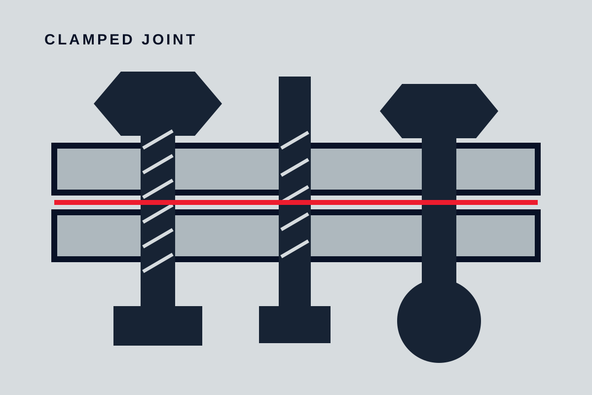
A good seal cannot compensate for excessive shaft runout, worn bearings, misalignment, pipe strain, vibration, or damaged fits. Verify the pump and driver condition before attributing repeated leakage solely to seal selection.
Installation requires clean parts, protected faces, correct setting dimension, appropriate lubricant on secondary seals when permitted, controlled fastener tightening, and accurate piping connections. Do not touch lapped faces or reuse damaged secondary seals.
Record the installed seal identification, setting, support-system charge, valve lineup, commissioning observations, and baseline leakage. This turns later troubleshooting into evidence rather than guesswork.
Failure clues
| Observation | Possible mechanism | Check |
|---|---|---|
| Faces heat or fail soon after start | Dry running, trapped gas, no circulation | Priming, venting, chamber pressure, support flow |
| Carbon face chips | Vibration, handling, pressure shock, misalignment | Shaft movement, installation record, transients |
| Deposits around atmospheric side | Crystallisation or leakage evaporation | Quench, temperature, leakage path, cleaning |
| Elastomer swollen or hard | Chemical or temperature incompatibility | Actual fluid mixture, cleaning chemicals, material record |
| Repeated leakage with good faces | Shaft runout, bearing wear, incorrect setting | Equipment condition and installation dimensions |
| Barrier system alarms | Loss of pressure, level, circulation, or cooling | System valves, instruments, cooler, refill procedure |
Preserve faces, elastomers, deposits, and orientation during investigation. Wear pattern can distinguish alignment, heat, abrasion, and installation damage.
RFQ and selection checklist
- pump and chamber drawing, shaft size, speed, direction, runout, and movement;
- chamber pressure and temperature for normal and transient conditions;
- complete fluid properties, solids, vapour behaviour, lubricity, corrosion, and deposits;
- leakage consequence, containment objective, detection, drain, and alarm response;
- single or dual arrangement and the purpose of any flush, quench, or barrier system;
- face, secondary seal, metal, gasket, and support-fluid compatibility;
- support piping, pressure, flow, cooling, cleanliness, instrumentation, and utilities;
- start-up, venting, dry-run prevention, standby, cleaning, and shutdown procedure;
- drawings, material records, test scope, installation instructions, spares, and failure support.
A reliable mechanical seal selection connects every component to a stated process condition or containment need. If the chamber and support system are missing from the specification, the seal has not been selected as a system.
Define the fluid conditions
Record vapour pressure, solids, crystallisation, lubricity, toxicity and temperature at the seal chamber. Conditions there may differ from the pump suction or discharge. Transients during startup, cleaning and standby can be more demanding than steady operation.
Choose faces and arrangement
Face materials balance wear, heat transfer, chemical resistance and dry-running tolerance. A single seal may suit clean non-hazardous service. Dual arrangements can isolate the process or control emissions but require a correctly designed buffer or barrier system.
Support reliable operation
Check chamber geometry, flush plan, venting, shaft runout and bearing condition. Installation cleanliness matters because small face damage or contamination can create a persistent leak. Keep the specified setting dimensions and test procedure with the equipment record.