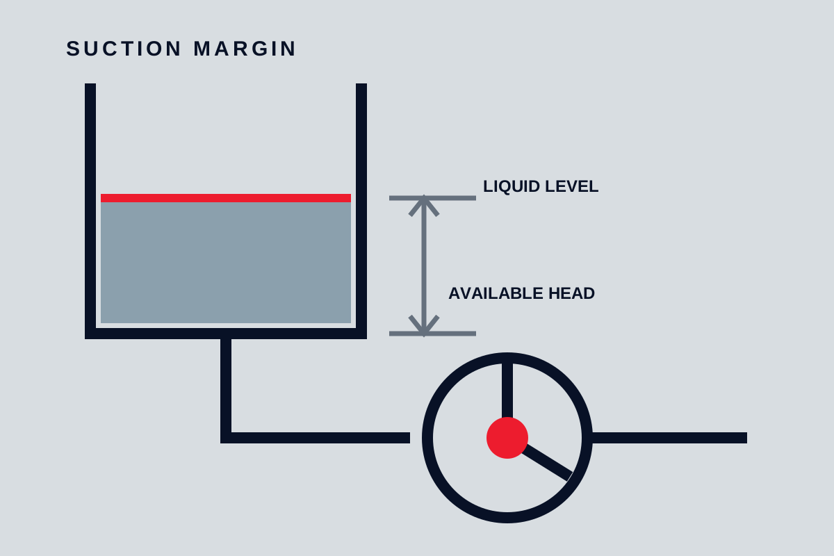
Net positive suction head is a way to express how much suction-side pressure remains above the liquid’s vapour pressure at the pump reference point. Buyers do not need to treat it as an abstract catalogue term: it is the margin that helps liquid remain liquid as it enters the pump. If that margin becomes too small, vapour can form in low-pressure regions and collapse as pressure recovers, reducing performance and potentially damaging the pump.
Available versus required
NPSH available belongs to the installation. It depends on pressure acting on the liquid surface, vertical relationship between liquid level and pump, suction-pipe losses, and the liquid’s vapour pressure at the actual temperature. It changes as a tank empties, a filter fouls, flow rises, ambient pressure changes, or the liquid gets hotter.
NPSH required belongs to a particular pump configuration at a particular speed and flow under defined test conditions. It is established from a performance criterion, not from a promise that cavitation is completely absent. The value commonly rises as centrifugal-pump flow increases, and it can change with impeller geometry, speed, and internal condition.
The basic selection comparison is:
NPSH available must exceed NPSH required by a margin appropriate to the service, uncertainty, and consequence.
That statement is more useful than applying a universal allowance. A cold-water transfer pump with stable tank level is different from a hot volatile liquid near its boiling condition, a high-energy pump, or a service in which small performance loss is unacceptable.
What creates available suction margin
Start at the liquid surface and follow the flow path to the pump inlet. Pressure on the surface contributes to available margin. A liquid level above the pump adds static head; a pump above the liquid level subtracts it. Friction through pipe, valves, strainers, fittings, and entrance geometry consumes margin. Vapour pressure also subtracts from the usable pressure because it represents the point at which the liquid begins to form vapour.
The most important variables are therefore practical installation data:
- minimum and maximum liquid level;
- vessel pressure or credible vacuum condition;
- liquid temperature range and corresponding vapour behaviour;
- minimum atmospheric pressure when the vessel is open;
- suction-pipe diameter, length, fittings, valves, and strainers;
- flow range, including start-up and maximum-demand cases;
- elevation and the exact point used as the pump reference.
Use consistent units and a consistent pressure basis. Mixing gauge and absolute pressure is a common and serious error because vapour pressure and atmospheric pressure are absolute quantities. Confirm the manufacturer’s stated reference plane before comparing values.
Why temperature and level matter
Hotter liquid generally has higher vapour pressure, leaving less pressure margin before vapour forms. A system that works with cool commissioning water may be unsuitable for the hotter process liquid. The check must use the highest credible liquid temperature at the suction, not a convenient room-temperature data sheet.
Falling tank level reduces static suction head. If the normal duty is calculated from a full tank while the pump must continue operating near empty, the available margin is overstated. Vortex formation at low level can also introduce gas even when the pressure calculation appears acceptable.
For a closed vessel, process pressure may help or harm the margin. A pressurised vessel can add suction pressure; a vessel drawn into vacuum can remove it. Control-system set points, relief or vent behaviour, and abnormal conditions should be reconciled with the mechanical calculation.
Suction losses are flow-dependent
Friction loss increases strongly as velocity rises. A suction line that is acceptable at normal flow may consume much more margin at the maximum duty. Strainer fouling, a partly closed valve, a collapsed hose, or a temporary screen can add losses that were absent from the clean-line calculation.
Keep the suction path short, direct, and generously sized where practical. Avoid arrangements that trap gas. Use reducers and fittings in orientations that do not create persistent air pockets or severe inlet distortion. Long-radius changes and adequate straight approach may help sensitive pumps, but the manufacturer’s inlet guidance should govern the final arrangement.
A pressure gauge near the pump can support commissioning and troubleshooting, but gauge readings must be interpreted with elevation, velocity, and absolute-pressure basis in mind. A stable gauge does not by itself prove that local low-pressure zones inside the pump are harmless.
NPSH required is not a no-cavitation line
The published value is normally tied to a defined test observation such as a change in head. Vapour formation can begin before that criterion is reached, and local cavitation may still affect noise, vibration, erosion, or seal and bearing loads. Conversely, an occasional faint sound does not prove that cavitation is the only problem; air ingress, recirculation, solids, or mechanical faults can sound similar.
Read the curve at the actual flow and speed. Do not take one minimum number from a brochure and apply it across the full operating range. Confirm whether the value is based on water or another test liquid and whether corrections or special definitions apply to the proposed pump type.
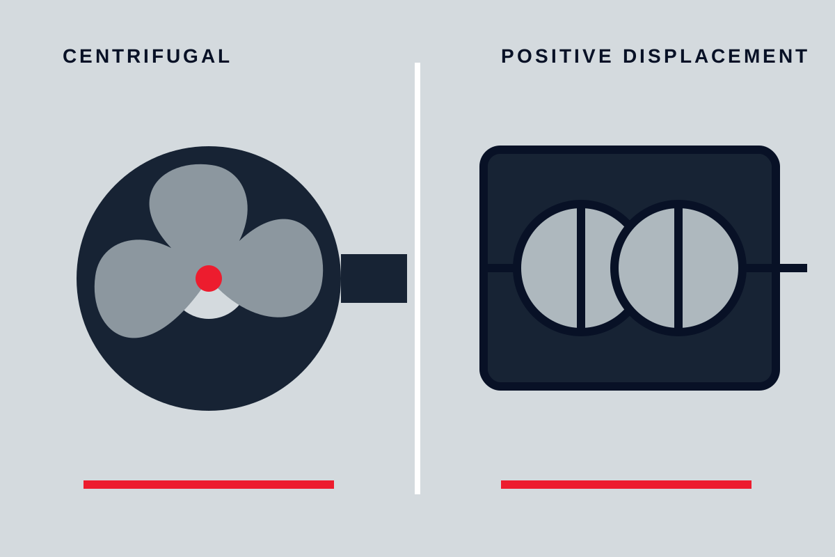
For positive-displacement pumps, inlet capability may be expressed differently, but the underlying concern remains: the chambers must fill without the liquid flashing or the inlet starving. Viscosity, speed, acceleration, and port losses can dominate. The comparison with centrifugal pump behaviour should therefore include inlet conditions, not only discharge pressure.
Symptoms of inadequate suction performance
Possible indicators include crackling or gravel-like noise, unstable discharge pressure, falling flow, erratic power, vibration, loss of prime, damaged impeller surfaces, or repeated seal and bearing problems. None is unique to NPSH deficiency.
Use a sequence rather than guessing:
| Observation | Check | Possible response |
|---|---|---|
| Problem worsens as tank empties | Liquid level, vortex, suction lift | Raise minimum level, improve submergence, or lower pump |
| Problem worsens at high flow | Suction loss and NPSHr at actual flow | Reduce losses, enlarge line, reduce flow, or reselect pump |
| Problem appears when liquid is hotter | Actual temperature and vapour pressure | Reduce temperature where possible or increase suction pressure |
| Unstable flow after maintenance | Air leaks, venting, valve position, strainer | Restore tightness, prime correctly, and remove restrictions |
| Damage concentrated in low-pressure regions | Operating point and cavitation assessment | Correct duty or select suitable hydraulic geometry |
Before changing equipment, verify the process conditions and instrument accuracy. A throttled discharge may reduce flow and suction demand, but it should be used as a diagnostic clue, not automatically accepted as the permanent solution.
How to improve the margin
System changes can increase available margin: raise liquid level, lower the pump, increase vessel pressure where the process safely permits, reduce liquid temperature, enlarge or shorten suction piping, remove unnecessary restrictions, or reduce the maximum flow. Cleaning a fouled strainer is a maintenance action; designing a line that only works with a perfectly clean strainer is a specification risk.
Pump changes can reduce the required margin: select hydraulic geometry with lower inlet demand, operate at lower speed, choose a different pump size, use an inducer where properly engineered, or choose another pumping principle. Every change has consequences for efficiency, stable operating range, solids passage, power, and maintenance.
Do not solve a weak suction system only by adding an unexplained numerical allowance. The pump selection process should document the limiting case and show how the proposed design remains acceptable.
Buyer and RFQ checklist
Ask the supplier to mark the proposed duty points on the pump curve and provide NPSH required across the relevant flow range. State the liquid, temperature, speed, impeller or rotor configuration, and test basis. Provide the calculated available value for the worst credible case and identify the margin required by the project.
Before release, verify:
- the minimum liquid level and maximum temperature were used;
- vessel and atmospheric pressures use an absolute basis;
- suction losses include the maximum flow and credible fouling;
- the pump reference plane matches the supplier definition;
- operating points remain inside the allowed hydraulic range;
- start-up, standby, and abnormal conditions were reviewed;
- the proposed corrective action changes a real system variable rather than hiding uncertainty.
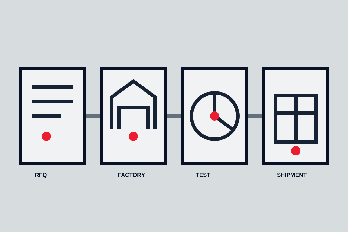
NPSH is not a property that can be checked from the pump data sheet alone. It is a relationship between liquid, installation, operating point, and pump. A good selection keeps that relationship visible from RFQ through commissioning.
Build a margin
The margin should reflect uncertainty, operating range, liquid sensitivity and the consequence of damage. Higher temperature increases vapour pressure, while a blocked strainer or lower tank level reduces inlet pressure. Check the worst credible combination instead of the commissioning condition alone.
Improve suction conditions
Shorten and enlarge suction piping, remove unnecessary fittings, prevent air pockets and locate the pump lower when practical. Confirm acceleration head for reciprocating systems and review transient conditions during startup or rapid valve movement.