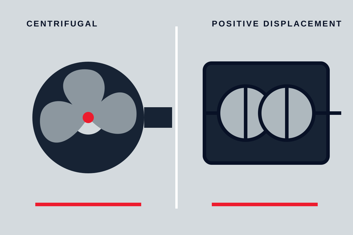
Centrifugal pumps are usually the practical first choice for clean, low-viscosity liquid at moderate pressure and steady flow. Positive displacement pumps become stronger candidates when viscosity is high, flow must remain closely tied to speed, pressure is high relative to flow, or accurate low-rate transfer matters. The correct choice depends on the complete operating envelope—not on which family can meet one quoted duty point.
Core differences at a glance
| Decision factor | Centrifugal pump | Positive displacement pump |
|---|---|---|
| How flow is produced | Adds velocity with an impeller, then converts velocity to pressure | Traps and moves repeated volumes |
| Response to system pressure | Flow moves along the pump curve as resistance changes | Flow changes less with pressure, subject to slip and compression |
| Typical flow character | Smooth, especially with rotary impellers | May be smooth or pulsating depending on design |
| Viscosity response | Performance and efficiency often deteriorate as viscosity rises | Many types handle viscous liquid effectively, but inlet filling and torque become critical |
| Closed discharge | Often moves toward shutoff with rising pressure and heating risk | Pressure can rise rapidly; independent relief protection is normally essential |
| Flow control | Throttling, speed change, impeller selection, bypass | Speed change, bypass, stroke change, or cycling depending on type |
| Common strengths | High flow, simple construction, broad general service | High pressure, viscous transfer, metering, low flow, self-priming in suitable designs |
These are family-level tendencies. A multistage centrifugal pump, air-operated diaphragm pump, internal gear pump, progressing cavity pump, and reciprocating metering pump have very different limits. Selection must move from family to actual design.
How the operating mechanisms differ
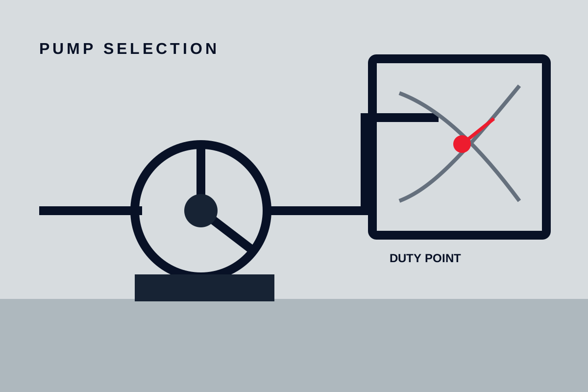
A centrifugal impeller accelerates liquid outward. The casing or diffuser converts part of that velocity into pressure. Flow is not fixed by each revolution; it settles where the pump curve intersects the resistance imposed by the system. Changing a valve position, tank level, pipe arrangement, speed, or impeller diameter moves the operating point.
A positive displacement pump encloses liquid in cavities and transports those cavities from inlet to outlet. The theoretical displacement per cycle is defined by geometry, so flow is closely related to speed or stroke. Real flow is lower because some liquid slips through clearances and because gas, compressibility, and incomplete filling reduce delivery.
This difference explains the most important safety distinction. Closing a centrifugal pump discharge usually drives the pump toward its shutoff condition, where internal heating and force still require control. Closing the discharge of a positive displacement pump does not stop the machine from displacing volume. If no safe flow path exists, pressure can rise until a component or driver fails. Relief protection must return liquid to a suitable destination and must not depend only on a control-system command.
System curves and operating range
Centrifugal-pump selection depends heavily on the system curve. Static head and friction determine the required head at each flow. The pump should operate in a stable region close to its preferred range during normal duty. Very low flow can cause internal recirculation and heating; excessive flow can increase power, vibration, velocity, and suction demand.
Positive displacement pumps are less governed by a conventional system-curve intersection because the pump attempts to deliver its displacement. System resistance appears mainly as differential pressure and required torque. The selection must therefore define maximum pressure, relief setting philosophy, viscosity range, allowable speed, and whether the inlet can fill the chambers at every condition.
Neither family should be selected from one normal point. Record start-up, shutdown, cleaning, cold liquid, hot liquid, minimum tank level, blocked-filter, minimum-flow, and maximum-throughput cases. The industrial pump selection guide describes the wider specification inputs.
Liquid properties
Low-viscosity liquid moves readily through a centrifugal impeller and casing. As viscosity rises, hydraulic losses increase and the published water-based curve may no longer predict flow, head, efficiency, or power accurately. A corrected performance estimate should use the actual viscosity range.
Viscosity can improve sealing across the internal clearances of some positive displacement pumps, reducing slip, but it also increases torque and makes chamber filling harder. Cold-start viscosity may be the limiting condition. Suction piping, speed, and port size must allow the liquid to reach the pump without excessive pressure loss.
Solids require design-specific analysis. A centrifugal slurry pump uses passages and wear materials intended for particles, while a close-clearance gear pump may be damaged by the same solids. A lobe or progressing cavity design may pass soft solids but can be sensitive to abrasion or dry running. Record particle size, hardness, concentration, shape, settling behaviour, and the consequence of product shear.
Entrained gas reduces centrifugal performance and may interrupt prime. Some positive displacement designs can move gas-liquid mixtures more predictably, but gas still changes volumetric accuracy, lubrication, temperature, and discharge behaviour. Do not treat self-priming as permission for indefinite dry operation.
Pressure, flow accuracy, and pulsation
Centrifugal pumps are effective when a process needs broad, smooth flow and the system can tolerate flow changing with resistance. Multiple stages can generate higher pressure, but the hydraulic and mechanical design must suit the duty. Flow measurement or control is still required when process accuracy matters.
Positive displacement designs can deliver flow that is repeatable relative to speed or stroke, making them useful for dosing and high-pressure, low-flow service. Accuracy depends on slip, compressibility, valve condition, viscosity, suction filling, and calibration. A displacement rating alone is not a guaranteed process flow.
Rotary designs may produce relatively smooth delivery; reciprocating designs create stronger pulsation. Pulsation affects instruments, pipe supports, valves, relief devices, and downstream process equipment. Dampeners can reduce pressure fluctuation but must be selected and maintained as part of the system.
Control and protection
Throttling a centrifugal-pump discharge moves the operating point to lower flow and higher head. It is simple, but the pressure loss represents energy that the valve dissipates. Variable speed can align pump output more closely with demand, provided the pump remains within its allowed flow, speed, power, and suction limits. A bypass may protect minimum flow but also consumes energy.
Positive displacement flow is commonly controlled by speed, stroke, controlled bypass, or start-stop operation. A throttling valve alone does not regulate displacement safely; it mainly increases differential pressure and power. Provide an independent relief path sized and routed for the credible blocked-discharge case. Consider thermal expansion of trapped liquid even when the pump is stopped.
Both families need suitable dry-run, low-level, seal, bearing, motor, and pressure protection according to consequence. Instrumentation should support a defined operating response rather than merely collect signals.
Maintenance and installation
Centrifugal pumps often have fewer close-clearance pumping elements and are familiar to many maintenance teams. Reliability still depends on alignment, pipe strain, suction conditions, minimum flow, balance, bearings, and seal-chamber environment. Wear can shift the curve and reduce efficiency before the pump visibly fails.
Positive displacement pumps may require inspection of gears, screws, rotors, stators, diaphragms, valves, packing, or timing elements. Clearances directly affect slip and performance. Some designs allow convenient cartridge replacement; others require careful timing or internal setting. Spare-part strategy should reflect the actual construction.
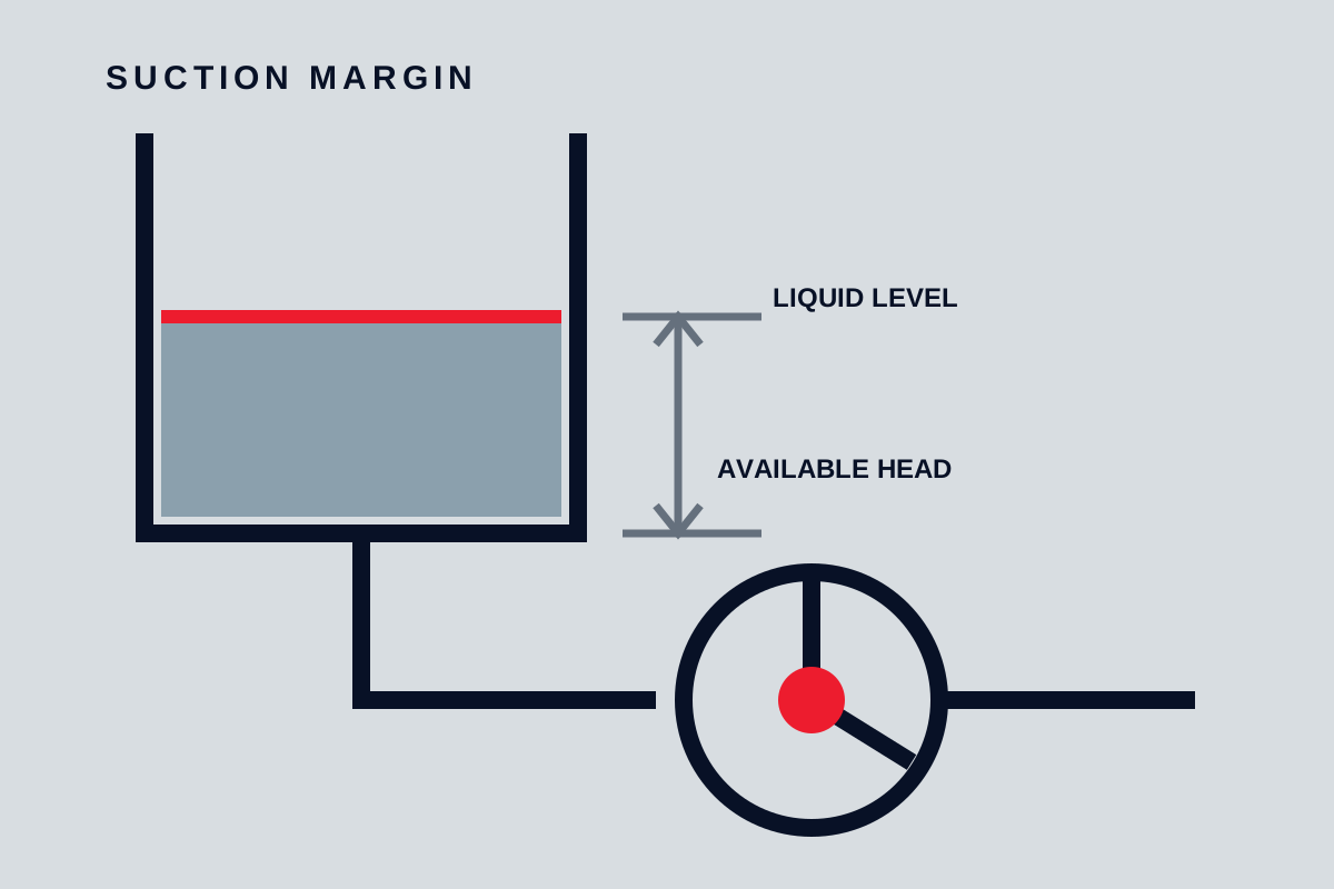
Installation differences are equally important. Centrifugal pumps need good inlet flow and adequate NPSH margin. Positive displacement pumps need low inlet resistance, sufficient filling time, a safe relief path, and piping that can tolerate pulsation where present. Both need accessible drains, vents, guards, supports, and maintenance space.
When to choose each family
Choose a centrifugal pump when most of these conditions apply:
- the liquid is relatively clean and low in viscosity;
- flow is medium to high and smooth delivery is desirable;
- system resistance naturally determines flow or can be controlled by speed or a valve;
- the operating range fits a stable portion of an available pump curve;
- maintenance simplicity and broad service familiarity are valuable.
Choose a positive displacement pump when most of these conditions apply:
- viscosity is high or changes enough to undermine centrifugal performance;
- the duty combines relatively low flow with high differential pressure;
- flow must track speed or stroke closely;
- the service involves dosing, transfer of shear-sensitive product, or controlled displacement;
- an appropriate design can handle the solids, gas, or self-priming requirement.
Avoid forcing either family into unsuitable conditions. A centrifugal pump is a poor answer when the required duty lies outside a stable operating range. A positive displacement pump is unsafe without effective overpressure protection and adequate inlet filling.
Final decision checklist
Before selecting, compare both families against the same data:
- minimum, normal, and maximum flow and differential pressure;
- density, viscosity at all temperatures, vapour behaviour, solids, gas, and shear sensitivity;
- suction pressure, line losses, priming, and minimum tank level;
- control method, relief path, minimum-flow needs, and blocked-line scenarios;
- power and torque across normal, start-up, and upset conditions;
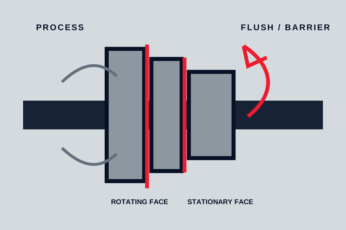
- seal or containment needs, leakage consequence, and dry-run risk;
- pulsation, noise, vibration, pipe support, and instrumentation;
- maintenance skills, wear parts, cleaning, spares, and expected inspection intervals.
The right pump is the one whose mechanism remains predictable across the real process envelope. Family labels narrow the search; duty data and risk controls complete the selection.
Making the choice
Compare efficiency across the real operating range, not only at one point. Include control valves or variable-speed drives, seal losses, pulsation, maintenance access and the consequences of dry running. The best choice is the pump whose operating envelope matches the whole process.