Choosing an industrial pump starts with the system, not the catalogue. A useful specification describes what the liquid must do, the conditions at the pump connections, and how the duty changes over time. Only then can a buyer compare pump families, sizes, materials, seals, drivers, and controls without treating a single headline flow rate as the whole requirement.
Define the real duty
Record minimum, normal, and maximum flow. For each condition, establish the pressure or head required at the pump discharge and the pressure available at the suction. Include static elevation, vessel pressure, piping friction, equipment losses, control valves, filters, and credible future changes. The result should be a set of operating points rather than one optimistic design point.
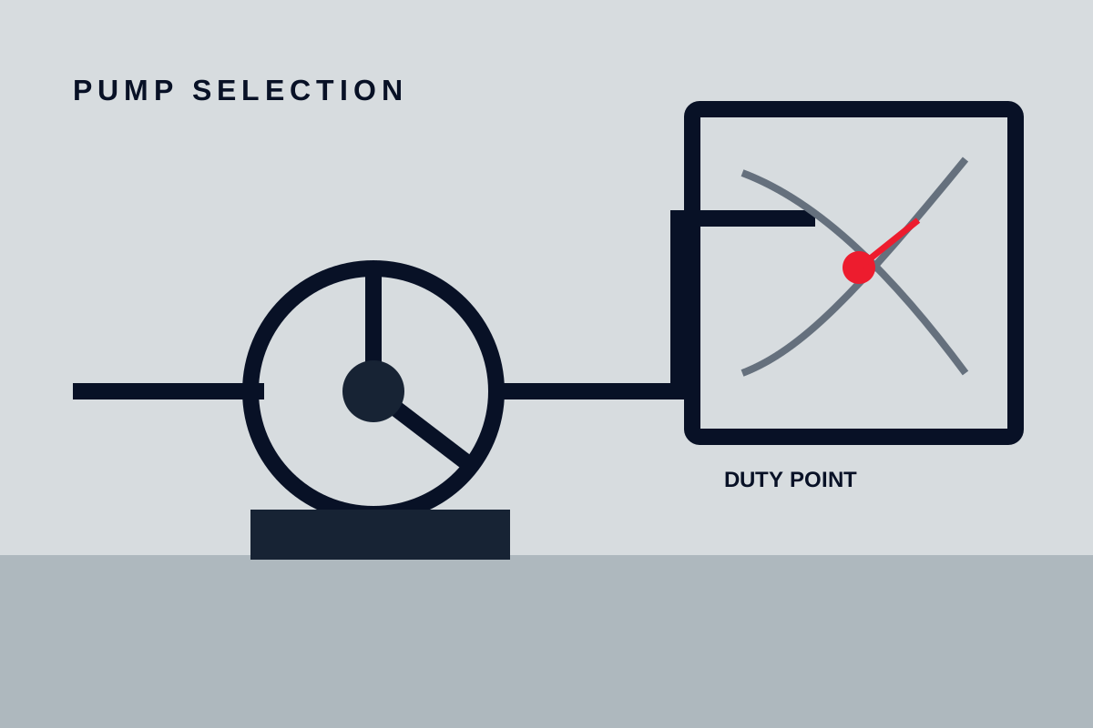
For a centrifugal pump, plot the system curve and compare it with the proposed pump curve at the intended speed and impeller diameter. Normal operation should sit in the stable region near the pump’s preferred operating range. A pump selected far to the right may overload its driver, lose suction margin, or experience high velocity and vibration. A pump selected far to the left may recirculate internally, run hot, and waste energy through throttling.
Do not add arbitrary head and flow margins independently. Oversizing can create as many problems as undersizing. If expansion is uncertain, describe the future case separately and decide whether a variable-speed drive, replaceable impeller, parallel pump, or later equipment change is the better response.
| Duty input | What to record | Why it changes selection |
|---|---|---|
| Flow | Minimum, normal, maximum, batch volume, cycle time | Sets pump size and control range |
| Differential requirement | Suction pressure, discharge pressure, elevation, losses | Establishes the actual duty point |
| Operating pattern | Continuous, intermittent, seasonal, standby | Changes thermal and maintenance requirements |
| Variability | Tank level, valve position, filter fouling, line changes | Defines the operating envelope |
Match the pump to the liquid
Describe the liquid at every operating condition. Density affects power and differential pressure. Viscosity changes friction loss and can reduce centrifugal-pump performance while increasing the torque required by positive-displacement designs. Vapour pressure affects suction margin. Solids size, concentration, hardness, and shape influence passage size, erosion, clogging, and seal choice. Entrained gas can interrupt normal pumping even when the liquid itself is easy to handle.
Chemical compatibility is more than choosing a body alloy. List every wetted component: casing, impeller or rotor, shaft or sleeve, fasteners exposed to the liquid, seal faces, elastomers, gaskets, and any coating. Include cleaning fluids, flushing liquid, start-up contamination, and off-spec batches. Temperature can change both corrosion behaviour and the allowable pressure or strength of non-metallic parts.
If the liquid crystallises, polymerises, settles, freezes, or becomes much more viscous when cool, specify shutdown and restart conditions. A pump that performs at normal temperature may still fail after a short standby period if the casing, seal chamber, or small-bore piping cannot be drained, flushed, or heated.
Choose the pumping principle
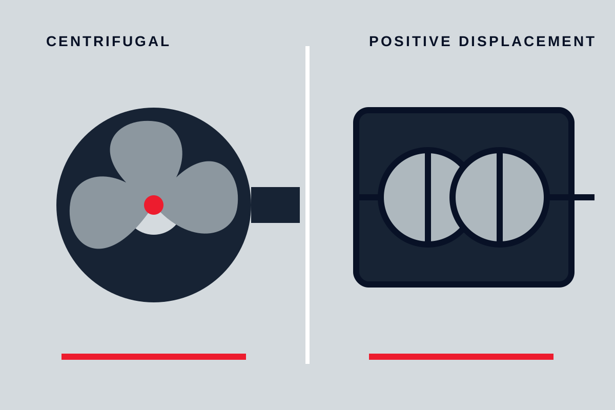
Clean, low-viscosity liquids at moderate pressure and steady flow often suit centrifugal pumps. Viscous transfer, accurate low flow, or a need for flow that changes predictably with speed may favour a positive-displacement pump. Solids-handling, shear-sensitive, gas-laden, sanitary, sealless, or abrasive services require a more specific comparison. The article on centrifugal and positive-displacement pumps explains the main behavioural differences.
Within a pump family, construction matters. An end-suction centrifugal pump, vertical sump pump, multistage unit, and magnetically driven process pump solve different installation and containment problems. Likewise, gear, screw, lobe, diaphragm, and reciprocating pumps do not behave identically simply because all are positive displacement.
Shortlist the principle by eliminating unsuitable options first. Ask whether the pump can pass the solids, tolerate the viscosity range, operate without damaging the product, provide the required pressure, and remain stable across the control range. Then compare efficiency, maintenance access, spare parts, and total installed cost among the remaining candidates.
Check suction conditions and cavitation risk
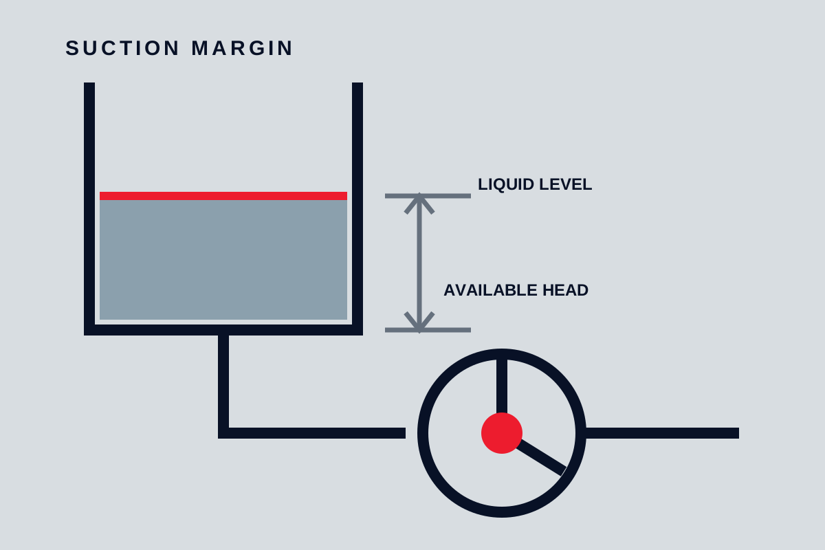
Suction performance is an installation property as much as a pump property. Determine the lowest liquid level, highest liquid temperature, lowest vessel pressure, highest required flow, and maximum suction-line loss that can occur together. Compare the resulting available suction margin with the pump manufacturer’s requirement across the operating range, not only at the normal point.
The catalogue value is obtained under defined test conditions and should not be treated as a universal safe margin. The required allowance depends on service severity, energy level, liquid sensitivity, and uncertainty. Review NPSH and pump suction conditions before accepting a selection with little margin.
Keep suction piping short and direct where practical. Avoid high points that trap gas, poorly arranged reducers, partially open isolation valves, undersized strainers, and elbows immediately at sensitive inlets. Confirm that the pump can be vented and primed. For positive-displacement pumps, also consider acceleration effects, inlet starvation, and the ability of a viscous liquid to fill the pumping chambers.
Select materials, sealing, and construction
Specify materials by required compatibility and mechanical duty rather than by a vague label such as corrosion resistant. Ask for the material of each pressure-containing and rotating wetted part, the manufacturing route, and the evidence required to verify it. If erosion is credible, review wall thickness, velocity, particle path, replaceable wear parts, and coating repair.
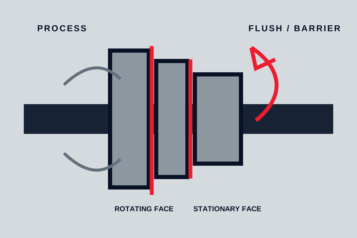
The shaft sealing arrangement should match leakage consequence, liquid lubricity, solids, vapour behaviour, temperature, and maintenance capability. A simple packed gland may be maintainable in water service where controlled leakage is acceptable. A single mechanical seal needs suitable lubrication and stable seal-chamber conditions. Dual seals, external flushes, or sealless designs add equipment and operating requirements that must be specified as a complete system.
Also define nozzle orientation, flange or connection details, allowable external loads where relevant, drainage, venting, baseplate, coupling, guard, and maintenance removal space. These details affect whether the selected pump can actually be installed and serviced.
Size the driver and control method
Check absorbed power across every permitted operating point and for the maximum credible liquid density or viscosity. The driver should cover the required load without encouraging a pump selection that is needlessly oversized. Record electrical supply, enclosure, ambient conditions, starting method, hazardous-area requirements when applicable, and any limits imposed by the control system.
Choose control around the process. Throttling is simple but dissipates pressure. Variable speed can reduce energy and expand control, but the pump must remain within acceptable speed, flow, and suction limits. Bypass control may protect minimum flow but returns energy to the system. On-off or batch control requires acceptable cycling and protection against running dry or against a closed discharge.
Define instrumentation and trips deliberately. Depending on consequence, useful signals may include suction and discharge pressure, flow, motor current, bearing temperature, leakage, vibration, tank level, or seal-support condition. A trip should have a stated purpose and response rather than being copied from another installation.
Compare offers on the same basis
Require each supplier to return a completed data sheet, marked performance curve, power curve, suction-performance information, materials list, sectional drawing, motor data, seal details, and stated deviations. Curves should identify speed, impeller or rotor configuration, and the liquid assumptions behind the prediction.
Do not compare purchase price before normalising scope. One quotation may exclude the baseplate, coupling, guard, motor, coating, testing, or documentation included by another. Identify spare parts, recommended commissioning spares, special tools, preservation, packing, and expected maintenance access.
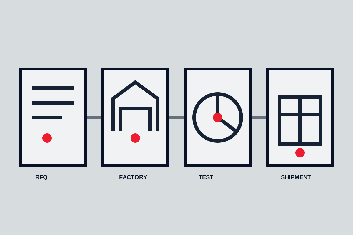
For critical equipment, define inspection and testing before order placement. The acceptance plan may cover document review, material records, dimensional checks, pressure testing, performance testing, vibration observations, coating, and final inspection. The exact requirements should match equipment risk and the governing project specification rather than a generic checklist.
Final pump specification checklist
Before issuing an RFQ, confirm that it states:
- minimum, normal, and maximum flow with corresponding suction and discharge conditions;
- liquid composition, density, viscosity, temperature, vapour behaviour, solids, and gas content;
- operating pattern, control philosophy, minimum-flow protection, and foreseeable future cases;
- suction-system arrangement and the required margin against cavitation or inlet starvation;
- wetted materials, seal arrangement, flushing or barrier services, and leakage limits;
- driver supply, ambient conditions, starting or speed control, and required instrumentation;
- installation orientation, connections, baseplate, coupling, guard, drainage, and maintenance space;
- required drawings, data sheets, material records, tests, inspection points, preservation, and spares.
A defensible selection is traceable: every important pump feature should answer a stated duty, risk, or maintenance need. If an offer cannot be checked against the operating envelope, the problem is incomplete specification rather than insufficient catalogue choice.
Check the installation
Available NPSH should exceed the pump’s required NPSH with a defensible margin. Review suction-pipe velocity, tank level, elevation and vapour pressure. Finally, specify seal arrangement, driver efficiency, control method, baseplate, instrumentation and the documentation needed for commissioning and maintenance.