Choose a gearbox from the driven load, not from motor power alone. The required output speed and torque establish the ratio and basic capacity; the actual choice then depends on duty cycle, shock loading, thermal capacity, shaft geometry, mounting, external shaft loads, environment, and maintenance access. A reducer that appears adequate at one steady operating point can still be unsuitable for frequent starts, reversing, high ambient temperature, or a belt drive imposing excessive radial load.
Start With the Load: Output Speed, Torque, and Duty Cycle
A gearbox reduces input speed and increases available output torque. It does not create power. Its purpose is to match a motor or other prime mover operating at a practical speed to a driven machine that needs lower speed, higher torque, or a different shaft orientation.
Collect driven-equipment data before comparing inline, right-angle, worm, planetary, or cycloidal arrangements. At a minimum, define:
- Required output speed in revolutions per minute (rpm), including the permitted operating range.
- Continuous running torque at the driven shaft, in newton-metres (N·m) or pound-foot (lb·ft).
- Starting torque, acceleration torque, transient overloads, and any expected jam or impact condition.
- Motor type, rated speed, allowable speed range, and torque curve. This is particularly important with variable-frequency drives (VFDs).
- Operating hours per day, starts per hour, reversals, dwell periods, and load variation through the cycle.
- Driven-load inertia where acceleration or deceleration is significant.
- Output shaft direction, mounting orientation, coupling or driven element, and radial and axial loads.
- Ambient temperature, contamination, washdown exposure, corrosive chemicals, and maintenance access.
A motor nameplate gives useful input information, but it is not a gearbox sizing result. A large motor can be lightly loaded; a smaller motor can produce damaging peak torque through a high-ratio reducer, a VFD, or an abrupt load change. Selection guidance from AutomationDirect similarly begins with required load torque and speed, followed by ratio, service factor, thermal torque, mechanical torque, and overhung-load checks.
The duty profile matters because gearbox ratings are conditional. A conveyor running steadily for long periods is evaluated differently from a mixer that starts under viscous material, a positioning axis that reverses repeatedly, or a crusher feed drive exposed to intermittent shock. Use the selected manufacturer’s rating tables and definitions for the actual gearbox series; service-factor methods are not automatically interchangeable between brands or product families.
Calculate Ratio and Output Torque Before Selecting a Gear Arrangement
The nominal reduction ratio is calculated from input and required output speed:
[ i = \frac{n_{in}}{n_{out}} ]
Where:
- (i) is the speed reduction ratio.
- (n_{in}) is gearbox input speed.
- (n_{out}) is required gearbox output speed.
For example, a motor operating at 1,500 rpm driving equipment at 50 rpm requires an approximate 30:1 overall reduction. If belts, chains, or external gears are also present, calculate the complete reduction path rather than assigning all reduction to the gearbox.
For rotational systems, mechanical power is related to torque and speed:
[ P = T\omega ]
where (P) is power in watts, (T) is torque in N·m, and (\omega) is angular speed in radians per second. In commonly used industrial units:
[ P,(kW) = \frac{T,(N\cdot m) \times n,(rpm)}{9550} ]
This equation is useful for checking whether the torque and speed requirement is consistent with available motor power. It is not a replacement for a load calculation or gearbox rating review.
In an ideal reduction, output torque would equal input torque multiplied by ratio. Actual output torque is lower because the gear set, bearings, seals, lubricant, and other internal components have losses:
[ T_{out} \approx T_{in} \times i \times \eta ]
where (\eta) is gearbox efficiency at the applicable speed, load, temperature, ratio, lubrication condition, and configuration.
Efficiency should not be treated as a fixed value for a gearbox type. In its application guide, Malloy Electric describes how gear arrangement affects efficiency and notes that operating losses vary with design and conditions. Use the efficiency data for the exact reducer family and ratio when it is available. This is especially important for high-ratio worm drives, multiple-stage reductions, low-speed operation, and applications where motor capacity or heat rejection is limited.
Separate at least four torque conditions in the calculation:
- Continuous running torque: the normal steady torque required by the load.
- Starting torque: torque needed to break away and begin motion, which can be materially higher for loaded conveyors, mixers, or static friction conditions.
- Acceleration and deceleration torque: torque required to change rotating or translating inertia within the required time.
- Peak or fault torque: short-duration overload from process disturbances, impact, plugging, emergency stops, or drive-control behavior.
A gearbox may have a mechanical output torque rating sufficient for a short peak but inadequate thermal capacity for continuous duty. Conversely, a thermally acceptable gearbox may not tolerate a high transient load. Both limits must be reviewed.
Match Gearbox Type to Shaft Geometry, Ratio, Efficiency, and Backlash
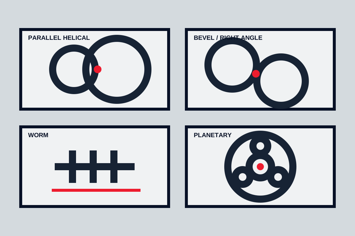
Gear arrangements are not interchangeable. Their geometry and internal load paths affect mounting options, ratio availability, efficiency behaviour, torque density, backlash, noise, and response to shock loading.
Inline helical gearboxes
Inline helical reducers place input and output shafts on the same axis. They are commonly considered where a straight-through layout is practical and efficient power transmission is important. Multi-stage helical units can provide substantial reduction, but the exact range, rated torque, and efficiency depend on the manufacturer’s design.
Helical gearing generally offers smooth tooth engagement compared with spur gearing. It can suit conveyors, process machinery, pumps, fans, and general industrial drives when shaft alignment and mounting space support an inline arrangement. Verify the output shaft load rating if sprockets, pulleys, or pinions are mounted directly on the reducer.
Bevel-helical and other right-angle gearboxes
Bevel-helical reducers change the shaft direction, normally by 90 degrees. They can solve layout constraints where the motor cannot sit inline with the driven shaft. Right-angle geometry can simplify some conveyor, mixer, and material-handling arrangements, but it does not remove the need to check torque, thermal limits, and external shaft loads.
A bevel-helical unit is often considered when a right-angle layout and relatively high efficiency are both required. However, the actual ratio range, permissible input speed, output torque, and mounting positions remain model-specific.
Worm gearboxes
Worm reducers also provide a right-angle drive and can achieve relatively high reduction in compact layouts. Their efficiency can be more sensitive to ratio, lead angle, lubrication, speed, and load than rolling-contact gear arrangements. The resulting heat generation can become a governing limit in continuous-duty applications.
Do not assume that a worm gearbox is self-locking. Backdriving behaviour depends on the exact geometry, friction conditions, load direction, vibration, wear, and manufacturer guidance. Where load holding is safety-critical or operationally necessary, specify and verify a suitable brake, backstop, or other retention method rather than relying on an assumed self-locking effect.
Planetary gearboxes
Planetary reducers use multiple planet gears to distribute load around a central sun gear. Their coaxial geometry and high torque density can make them useful where space is limited, inertia matters, or a compact inline package is required. They are frequently considered for servo axes, mobile equipment, winches, and high-torque compact drives, subject to the exact manufacturer ratings.
Positioning applications require more than a nominal backlash value. Check backlash under the relevant torque direction, torsional stiffness, load inertia, repeatability requirement, coupling compliance, and control system behaviour.
Cycloidal reducers
Cycloidal reducers use a different reduction mechanism from conventional involute gear trains. They may be considered for high reduction, compact torque transmission, or duties involving cyclic loading, but their backlash, torsional characteristics, efficiency, and permissible shock loading must be reviewed from the exact product documentation.
All gear drives require operating clearance. As the Practical Maintenance gearbox reference notes, backlash is normally required to allow running clearance in gear drives. The relevant question is therefore not whether backlash exists, but whether the reducer’s backlash and stiffness are acceptable for the machine’s positioning, reversing, and load-control requirements.
Apply Service Factor, Shock Load, and Thermal Capacity Separately
Service factor is a manufacturer-defined method for accounting for application severity beyond a simple steady running load. It may incorporate operating time, starts, reversals, shock, driven-machine category, and other conditions. It is useful only when applied according to the selected manufacturer’s definitions and tables.
Do not apply a generic multiplier from an unrelated catalog and assume the result is valid. Instead, document the duty and select a factor using the manufacturer’s method for the chosen gearbox family.
Mechanical and thermal ratings must then be checked separately:
- Mechanical output torque concerns the load-carrying capability of gears, shafts, bearings, and related components under stated conditions.
- Thermal output torque concerns the reducer’s ability to dissipate internally generated heat at the actual input speed, ambient temperature, mounting arrangement, and duty cycle.
The AutomationDirect selection sequence explicitly distinguishes a gearbox’s maximum thermal output torque from its maximum mechanical output torque after service factor. A valid selection must satisfy both checks, along with the relevant shaft-load limit.
Thermal risk increases where efficiency is lower, duty is continuous, ambient temperature is elevated, ventilation is poor, input speed is outside the rating basis, or the reducer is installed near other heat sources. VFD operation can add further complexity. Confirm permissible input speed, low-speed lubrication behaviour, motor torque availability, and the gearbox manufacturer’s VFD guidance for the exact model.
High-inertia starts, rapid reversals, emergency stops, and impact loading should be assessed from a torque-time profile where possible. If the machine can jam or receive process impacts, establish the expected peak torque and duration with the driven-equipment designer. A gearbox selected only from average power may not survive these events.
Check Mounting, Overhung Load, Environment, and Interfaces
An otherwise adequate reducer can be eliminated by installation constraints. Review the full mechanical arrangement before releasing a purchase order.
First, confirm the shaft geometry and mounting method: inline or right angle, foot-mounted or flange-mounted, solid or hollow output shaft, keyed connection, shrink disc, torque arm, or another attachment method. Confirm permitted mounting positions in the exact installation manual. Lubricant level, breather location, seal arrangement, and thermal performance can depend on orientation.
Second, calculate radial and axial shaft loads. Pulleys, sprockets, pinions, chain tension, belt tension, and coupling misalignment can impose loads that are independent of transmitted torque. Overhung load is not a generic gearbox attribute; it depends on the output shaft, bearing arrangement, load position, direction, speed, and applicable manufacturer correction factors. Compare the calculated load at the actual point of application with the specific gearbox rating.
Third, verify interfaces:
- Motor frame, flange, shaft diameter, keyway, and coupling arrangement.
- Rated input speed and any VFD operating range.
- Required output shaft diameter, hollow-bore size, and connection details.
- Brake, backstop, torque arm, encoder, or safety-device requirements.
- Drawing dimensions, service clearances, lifting points, and access for oil checks or replacement.
Finally, specify the environment. Dust, moisture, washdown chemicals, corrosive atmosphere, outdoor exposure, and temperature extremes may affect seals, coatings, lubricant selection, enclosure features, breather arrangements, and inspection intervals. A stated protection rating or material alone does not establish suitability; compare the product documentation with the project environmental specification.
Use a Duty-Based Selection Method for Common Industrial Drives
The following are screening approaches, not final sizing rules. Final selection still requires the exact load profile and gearbox documentation.
Conveyors
For conveyors, establish loaded and unloaded belt tension, drive pulley diameter, running speed, starts per hour, incline, material accumulation, and likely jam conditions. Continuous duty may make thermal rating important, while frequent starts can make acceleration torque and service factor more significant. If the drive uses a chain or belt on the gearbox output, calculate overhung load rather than assuming the reducer shaft is adequate.
Inline helical, shaft-mounted, or right-angle bevel-helical layouts may all be practical depending on physical arrangement. Select geometry after defining the conveyor drive layout and shaft-load condition.
Mixers and agitators
Mixer duty often changes with fluid viscosity, vessel condition, temperature, impeller geometry, and starting state. A mixer can require more breakaway torque than normal running torque, particularly after settling or at low temperature. Obtain torque-speed data, process-fluid information, and startup requirements from the mixer or process-equipment supplier.
Right-angle arrangements can be useful where the motor must be offset from a vertical mixer shaft, but the gearbox must also tolerate applicable thrust, radial load, and continuous thermal duty. Do not infer these capabilities from arrangement alone.
Pumps and fans
Pumps and fans may have relatively steady running duty, but their torque and power characteristics differ by machine type. Confirm the required speed range, operating point, fluid or gas conditions, system resistance, and rotating inertia. Variable-speed operation should be checked against both motor and gearbox input-speed limits.
For continuous operation, prioritize efficiency at the expected operating point, thermal capacity, bearing loading, lubrication requirements, and maintenance access. A compact reducer that runs acceptably in intermittent service may operate too hot in an enclosed continuous-duty installation.
Positioning axes
Positioning, indexing, and servo applications require review of ratio, backlash, torsional stiffness, inertia matching, reversing frequency, acceleration torque, and required positional accuracy. Planetary reducers are often evaluated for compactness and low-backlash configurations, but no arrangement guarantees accuracy without system-level analysis.
Check the reducer’s stated backlash condition, permissible input speed, output bearing capacity, and peak torque limits. Also account for coupling compliance, structural deflection, encoder location, brake response, and control tuning.
High-shock machinery
Crushers, presses, reciprocating equipment, impact conveyors, and similar machinery require explicit assessment of shock events and jam torque. The key questions are event magnitude, duration, frequency, direction, and whether the motor drive can limit torque before gearbox damage occurs.
A gearbox marketed for high torque density or shock resistance still needs a configuration-specific mechanical rating and service-factor review. Consider protective devices, torque limiters, controlled acceleration, backstops, and monitoring where the process can impose unpredictable overloads.
Release the Gearbox Only After a Rating and Installation Review
Before ordering, place the selected gearbox, motor, and driven-equipment data in one review record. Confirm the exact model and ratio rather than relying on a family-level description.
Use this minimum release checklist:
- Required output speed and the resulting exact ratio.
- Input motor speed, motor torque curve, and VFD speed range where applicable.
- Continuous, starting, acceleration, and peak output torque requirements.
- Mechanical output torque rating and thermal output torque rating under stated operating conditions.
- Efficiency basis, including the relevant ratio, load, speed, and lubricant conditions where published.
- Manufacturer service-factor method and the duty assumptions used.
- Permissible radial and axial shaft loads, plus the calculated external load condition.
- Mounting position, lubrication quantity and type, breather arrangement, and ambient-temperature limits.
- Motor interface, output connection, brake, backstop, coupling, and guarding requirements.
- Certified dimensional drawing, installation manual, lubrication schedule, and current rating table for the exact unit.
During installation or maintenance, isolate electrical and stored mechanical energy, prevent movement of suspended or driven loads, and follow site lockout/tagout procedures. Do not align couplings, remove guards, change lubricant, or alter mounting orientation beyond the gearbox manufacturer’s instructions.
The practical selection rule is straightforward: choose the gearbox only after its exact ratio, speed range, mechanical torque, thermal capacity, shaft loads, mounting position, and environmental limits have all been verified against the real duty cycle. If any input is uncertain—particularly load peaks, high inertia, frequent reversing, or external shaft load—treat that uncertainty as a design issue to resolve with the driven-equipment supplier and gearbox manufacturer before release.