

A coupling between a gearbox and driven machine should be selected from the duty at the gearbox output shaft, not from shaft diameter or motor nameplate power alone. The final choice must transmit continuous and transient torque at the actual output speed while remaining suitable for the shafts, expected misalignment, torsional behavior, environment, and maintenance arrangement. A catalogue torque rating is only one part of that check.
Start With the Gearbox Output Duty, Not the Motor Nameplate
The output side of a gearbox normally operates at lower speed and higher torque than the motor-to-gearbox connection. A coupling selected from motor speed, motor torque, or an input-side coupling size can therefore be unsuitable at the gearbox output.
Collect the following before comparing gearbox coupling types:
- Gearbox output speed in revolutions per minute (rpm).
- Continuous output torque and the highest expected transient torque.
- Power at the coupling location, if it is known.
- Gearbox output shaft drawing: diameter, tolerance, keyway, spline, taper, shoulder position, and usable shaft length.
- Driven-machine shaft drawing with the same details.
- Starting method, starts per hour, stopping duty, reversals, and expected overload events.
- Expected angular, parallel, and axial shaft movement.
- Ambient temperature, contamination, moisture, corrosion exposure, and hazardous-area requirements where applicable.
- Guarding, installation clearance, lubrication access, and whether an element must be replaceable without moving either machine.
This is consistent with the broad selection inputs identified in the Lovejoy Coupling Handbook, which include torque, speed, shaft size, load characteristics, environment, space, maintenance, starts and stops, reversal, alignment, and balancing.
Where power and speed are known, running torque can be estimated as:
[ T = \frac{9550P}{n} ]
where:
- (T) is torque in newton-metres (N·m),
- (P) is power in kilowatts (kW), and
- (n) is rotational speed in rpm.
For example, 30 kW transmitted at 100 rpm corresponds to approximately 2,865 N·m of running torque. This is not necessarily the coupling design torque. Startup, acceleration, jams, reversing, braking, and cyclic process loads may create higher torque. Use measured or documented load data where it exists, then apply the exact coupling manufacturer’s selection method for the intended service.
If power is not reliably known, do not derive a precise torque from a motor nameplate alone. Gearbox ratio, efficiency, operating point, motor control method, and process load all affect what reaches the output coupling.
Compare Gearbox Coupling Types by Mechanical Trade-Offs
There is no universal best coupling type for a gearbox output. The suitable family depends on what the system needs to tolerate or control. Torque density, misalignment capacity, damping, stiffness, backlash, maintenance, and available space frequently pull the selection in different directions.
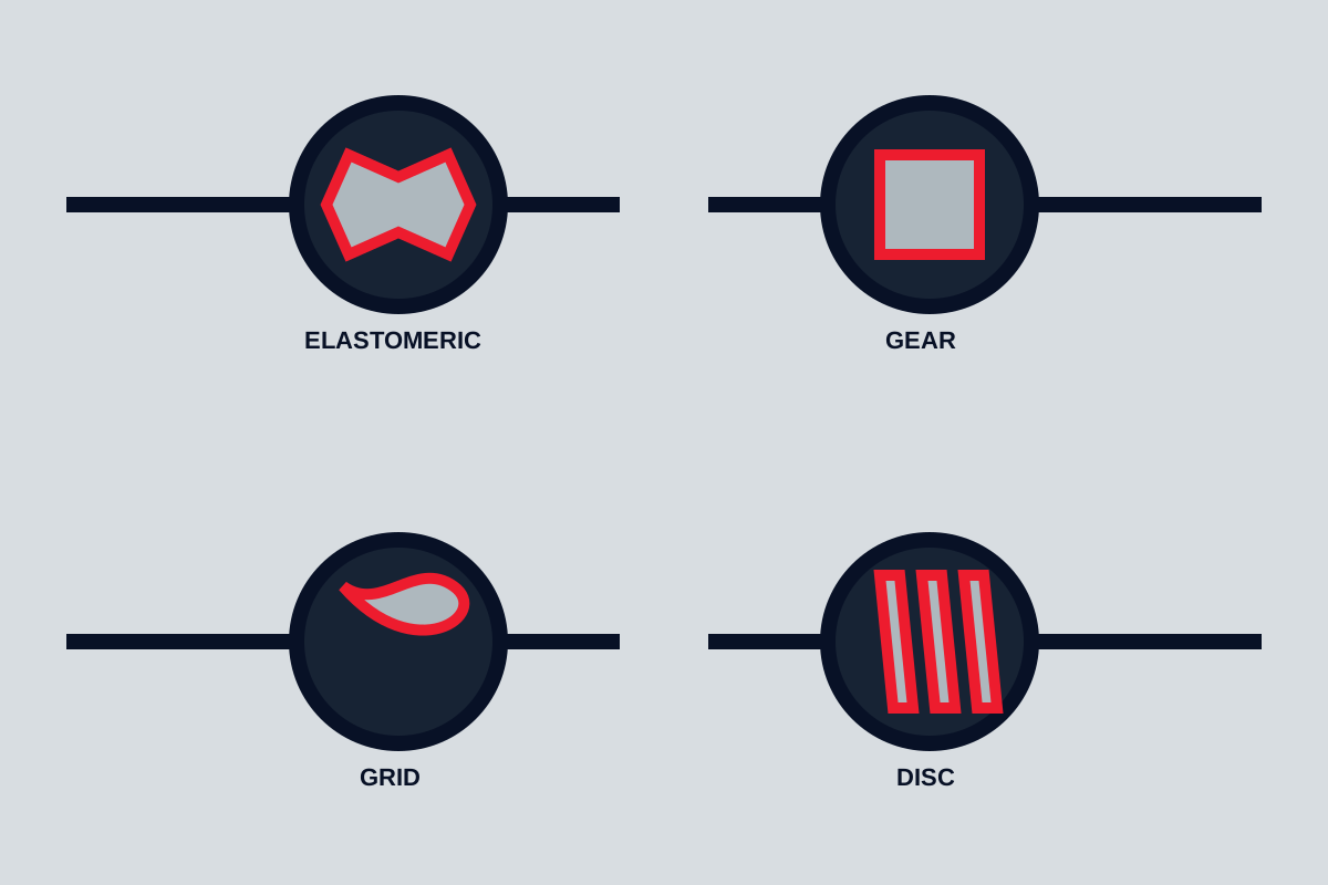
| Coupling family | General characteristics | Typical limitations to verify |
|---|---|---|
| Rigid coupling | High torsional stiffness and simple construction. Suitable only where shafts can be held in very accurate alignment and axial movement is controlled. | Alignment error, thermal growth, assembly access, and transmitted bearing loads can make it unsuitable. |
| Elastomeric coupling | Uses a polymer element to provide torsional compliance and some damping. Many designs can accommodate moderate misalignment without lubrication. | Element temperature range, chemical compatibility, torque derating, stiffness, backlash, and element replacement access vary by design. |
| Grid coupling | Metallic grid element can provide flexibility and may be used in duties involving shock loading. | Lubrication, sealing, cover condition, alignment limits, and maintenance requirements depend on the product design. |
| Gear coupling | Often provides high torque capacity in a compact envelope and can accommodate shaft misalignment through toothed hubs and sleeves. | Lubrication, seal integrity, backlash, balance, bore capacity, and maintenance access need review. |
| Disc coupling | Metallic flexible discs or diaphragms can provide high torsional stiffness and no-lubrication operation in many configurations. | Misalignment limits, fatigue duty, spacer arrangement, fastener access, and balance requirements must match the exact model. |
| Other metallic-flexible designs | Bellows, beam, and diaphragm arrangements may be used where torsional stiffness, low backlash, precision, or particular geometry matters. | Torque range, fatigue performance, shaft movement, and overload tolerance are highly design-specific. |
As general context, Machine Design notes that gear couplings can offer high torque capacity in compact sizes, followed by metallic-flexible categories such as grid and disc couplings. That does not establish a rating for any individual model, nor does it make compactness the correct priority for every installation.
A rigid coupling is not a low-cost substitute for a flexible coupling when the machines have separate foundations, measurable thermal growth, or practical difficulty holding alignment. Rigid designs transfer shaft position errors directly into connected equipment. The AGMA discussion of rigid couplings also highlights their construction and assembly constraints. Use one only when the machinery designer confirms the alignment and movement conditions.
An elastomeric coupling is not automatically the answer for vibration or shock. Its damping and torsional stiffness depend on the element material, geometry, temperature, preload, and frequency of the applied load. A metallic-flexible coupling is not automatically maintenance-free either; inspect the exact installation and operating instructions rather than assuming performance from the family name.
Size for Continuous Torque, Transients, Reversing, and Shock Loading
Separate the torque values that describe the duty:
- Continuous running torque is the normal transmitted load during stable operation.
- Starting or breakaway torque is the load needed to accelerate the driven inertia or overcome static process resistance.
- Peak torque may occur during jams, emergency stops, clutch engagement, abrupt speed changes, or process disturbances.
- Reversing torque applies when the rotation direction changes, particularly with frequent cycles or backlash-sensitive drives.
- Cyclic torque is an alternating component superimposed on the average torque, common in reciprocating, indexing, crushing, rolling, and pulsating process duties.
Use the coupling manufacturer’s published nominal, continuous, and maximum torque definitions for the exact candidate. These labels are not standardized enough to be treated as interchangeable between brands or coupling families. A stated maximum torque may be a short-duration structural limit, not an allowable repeated operating torque.
The relevant selection principle is that permissible coupling load should not be exceeded in any operating condition. KTR’s DIN 740 Part 2 selection guidance also states that coupling torque values apply to the coupling itself and that the shaft-hub connection requires separate investigation.
Do not use a generic service factor copied from an unrelated catalogue. The appropriate factor can depend on the prime mover, driven load, daily running time, frequency of starting, shock severity, and coupling construction. Obtain the candidate supplier’s current selection procedure and document which condition sets the selected size.
For a high-inertia conveyor, mixer, crusher, fan, mill, or reciprocating machine, request the driven-equipment torque curve or enough information to calculate acceleration and cyclic loads. If overload protection is installed, also establish its actual trip setting and response behavior. A coupling may survive normal process torque but still be damaged before a protective device reacts to a jam.
Check Speed, Shaft Geometry, and Connection Capacity Before Finalizing the Size
A coupling can pass a torque comparison and still fail the mechanical interface check. The selected hubs must physically fit both shafts and transfer load without exceeding the manufacturer’s bore, keyway, clamp, spline, or interference-fit limits.
Verify each of these items against current drawings and the exact coupling model:
- Maximum permitted bore for each hub material and hub style.
- Minimum hub engagement length on the shaft.
- Shaft diameter and tolerance.
- Key size, keyway depth, key material, and available key engagement length.
- Spline standard, fit class, and contact length where splined shafts are used.
- Taper details and locking method for tapered shafts.
- Clamp screw arrangement, tightening procedure, and required torque where keyless clamping hubs are used.
- Shaft shoulders, fillets, seal locations, and any interference with hub faces.
- Maximum operating speed, balancing grade, and any balance-related restrictions.
- Coupling outside diameter, guard clearance, and spacer length.
The shaft-hub connection deserves its own engineering check. A coupling’s nominal torque capacity does not prove that a particular key, spline, shrink fit, or clamping arrangement can transmit the required torque. The connection may be limited by key shear, hub wall thickness, shaft stress concentration, fretting, contact pressure, or insufficient engagement.
Speed matters even on a gearbox output that appears slow. Large diameter couplings can develop meaningful peripheral speed, and some products require a particular balance condition above specified rpm. Check the manufacturer’s maximum speed for the actual bore and configuration, including spacer, guard, and balance condition. Do not transfer a high-speed rating from a smaller bore or a different hub arrangement.
Match Misalignment Capability to Installed Shaft Geometry
Flexible couplings compensate for limited shaft movement; they do not remove the need for proper alignment. Establish the installed geometry and expected movement in three directions:
- Angular misalignment: shaft centre lines meet at an angle.
- Parallel or offset misalignment: shaft centre lines remain parallel but are displaced.
- Axial movement: the shaft ends move toward or away from each other.
Catalogue values should be treated as allowable operating limits under stated conditions, not as installation targets. The permitted combination may reduce when angular and offset misalignment occur together, when speed rises, when torque is high, or when long element life is required.
Start with a cold alignment target based on the equipment supplier’s instructions. Then account for expected thermal growth, baseplate distortion, foundation movement, pipe strain, and process movement. A pump, gearbox, and motor can align accurately when stopped yet run with unacceptable offset after temperature stabilizes.
Review the exact coupling installation manual for the method used to measure alignment, acceptable cold settings, hub gap, axial setting, and combined-condition limits. Laser alignment equipment can improve measurement, but it cannot determine the correct target without the machinery’s movement data.
Where the driven equipment is a pump, compressor, fan, or other machine with bearing-load limits, ensure that the proposed coupling and alignment condition do not impose loads beyond the machine manufacturer’s allowance. If those limits are unavailable, obtain them before accepting a coupling based only on its advertised misalignment capability.
Choose Torsional Stiffness and Damping for the Driven Load
Torsional stiffness describes how much a coupling twists under torque. Damping describes how it dissipates part of torsional vibration energy. Both affect the drivetrain, but neither is inherently better.
A comparatively compliant elastomeric coupling may help reduce transmission of certain torsional disturbances and shock events. It may also change natural frequencies, angular positioning behavior, and torque response. A relatively stiff disc or other metallic-flexible coupling may suit applications requiring low backlash or more direct torque transmission, but can transmit torsional disturbances differently.
The required behavior depends on the complete system: motor or engine, gearbox, coupling, driven inertia, load cycle, speed range, and control system. Review torsional stiffness, damping, backlash, and temperature-related derating from the selected coupling manufacturer’s published data. Do not assume that all elastomer elements have the same damping or that all metallic designs have the same stiffness.
Request application-specific engineering review when the system includes any of the following:
- Reciprocating compressors, pumps, or engines.
- Frequent reversing or indexing.
- High-inertia starts and stops.
- Variable-speed-drive operation across a wide speed range.
- Resonance concerns, cyclic torque, or noise and vibration limits.
- Positioning accuracy or backlash-sensitive machinery.
- Gearbox, motor, coupling, or driven-equipment documentation requiring torsional analysis.
A torsional analysis may show that changing coupling stiffness moves a critical speed into, or away from, the operating range. This cannot be determined reliably from nominal torque capacity alone.
Verify Installation Access, Environment, and Maintenance Before Ordering
The best coupling on paper can be difficult or unsafe to operate if it cannot be installed, aligned, guarded, inspected, or serviced in the actual machine layout.
Before purchase, review a drawing or model that confirms:
- Clearance for hub installation and removal.
- Shaft separation distance and required hub gap.
- Whether a spacer is needed to remove a pump, seal cartridge, or driven machine without moving the gearbox.
- Access to fasteners, clamping screws, lubrication points, and inspection covers.
- Ability to replace an elastomer element, grid, sleeve, disc pack, or other wearable component.
- Guard design, guard removal procedure, and clearance from rotating parts.
- Exposure to water, abrasive dust, chemicals, washdown, ultraviolet light, temperature extremes, or corrosion.
- Compatibility of elastomer elements, lubricants, seals, coatings, and fasteners with the site environment.
Lubricated couplings need an achievable lubrication and inspection plan. A sealed design may reduce routine lubrication work, but seal condition, lubricant compatibility, and inspection intervals remain product-specific. Likewise, an elastomeric element should be checked for the actual temperature and chemical exposure rather than selected on general assumptions about polymer performance.
During installation and maintenance, isolate electrical, hydraulic, pneumatic, gravitational, and rotational energy according to site procedures. Do not work on a coupling or remove a guard until the equipment is locked out, stored energy is controlled, and the machinery is safe to access. Install the guard and follow the coupling and machinery manufacturers’ tightening, alignment, lubrication, and inspection instructions before returning the drive to service.
A Practical Selection and Acceptance Rule
Choose a candidate coupling only after it passes all of the following checks for the exact model, hub configuration, and operating condition: continuous torque, peak and reversing torque, speed, bore and shaft-hub connection capacity, combined misalignment, axial movement, torsional requirements, environment, and maintainability. Then confirm that the installed shaft geometry, hub fit, fastener procedure, lubrication requirement, and guarding arrangement match the manufacturer’s documentation.
If the duty includes high inertia, shock, frequent reversals, variable speed, reciprocating loads, or uncertain shaft movement, treat catalogue selection as a starting point. The gearbox, coupling, and driven-machine manufacturers—or a qualified rotating-equipment engineer—should review the final arrangement before release.