An industrial gearbox changes speed and torque while establishing the position and direction of input and output shafts. Helical, bevel, worm, planetary, and shaft-mounted arrangements differ in load path, efficiency, ratio, stiffness, backlash, heat, and installation. Selection should begin with the driven-machine torque-speed duty and shaft geometry, not a preferred gearbox label.
What a gearbox must do
Most applications reduce motor speed and increase available output torque, but a gearbox also supports shafts, reacts gear forces, manages lubrication, and transmits dynamic loads. It may need to reverse direction, turn power through a right angle, split power, or fit directly onto a driven shaft.
Define continuous torque, peak torque, starting and stopping events, reversals, load inertia, operating hours, input and output speed, ratio, and duty variability. Include loads created by jams, brakes, back-driving, or emergency stops. A service factor is meaningful only when these events are described.
Thermal capacity can limit a gearbox before tooth strength does. Churning, sliding, bearings, seals, and inefficient mesh generate heat. Ambient temperature, airflow, mounting, oil volume, and duty cycle determine whether the housing can reject it.
Parallel-shaft helical gearboxes
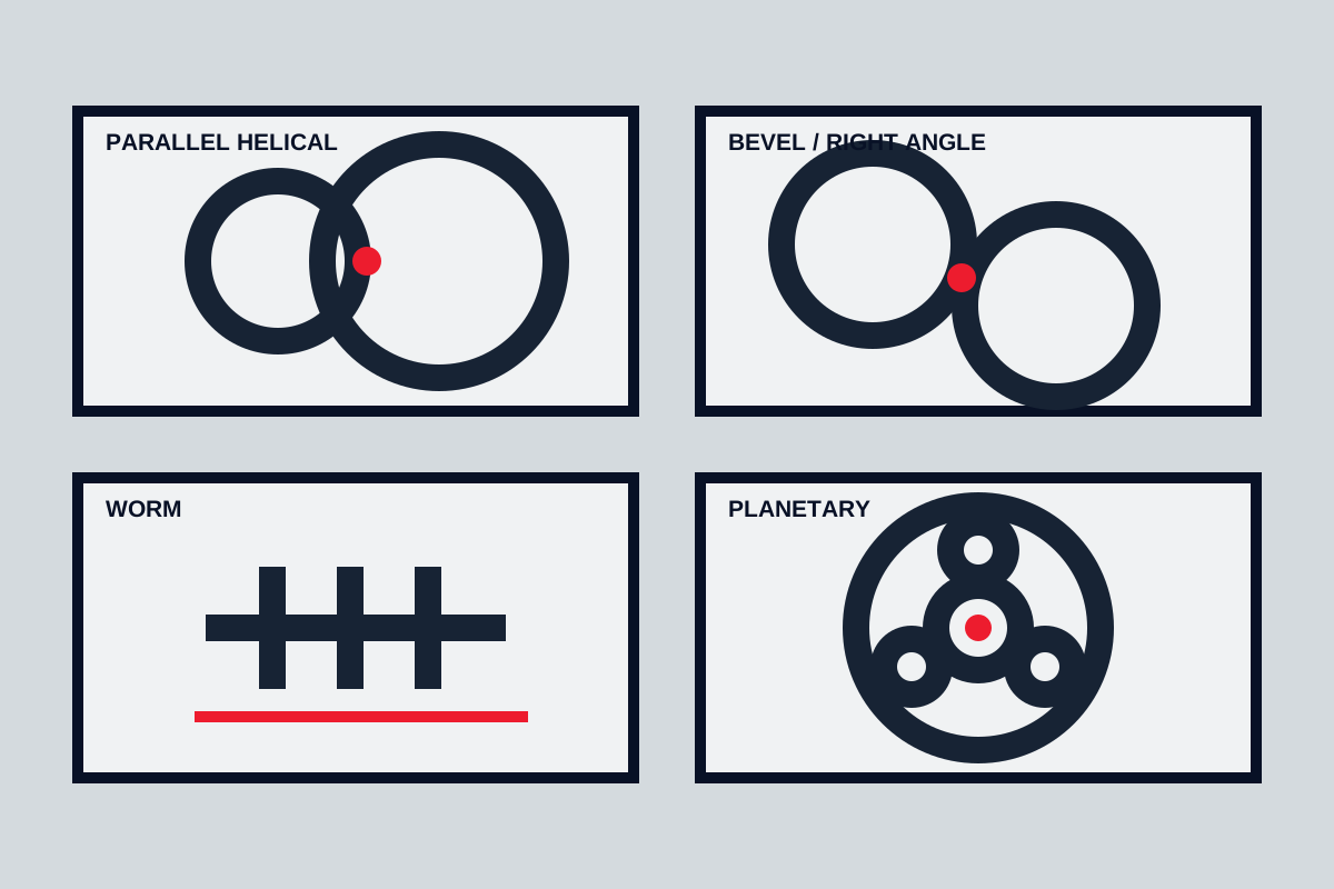
Helical teeth engage gradually, sharing load across more than one tooth and supporting smooth, efficient power transmission. Parallel-shaft units keep input and output axes parallel and can combine several reduction stages. They are common on conveyors, mixers, pumps, and process machinery.
Helical mesh creates axial thrust as well as radial gear forces. Bearings and housing must react those loads. Multiple stages provide useful ratios but add bearings, seals, and mesh losses. Backlash, torsional stiffness, and noise depend on accuracy, housing support, lubrication, and load.
Choose this arrangement when efficiency, broad industrial availability, and parallel shafts fit the machine layout. Check external shaft loads from belts, chains, couplings, and overhung equipment separately from transmitted torque.
Bevel and bevel-helical gearboxes
Bevel gears transmit power between intersecting shafts, commonly through a right angle. Bevel-helical gearboxes combine a bevel stage for direction change with helical stages for reduction. They suit conveyors, mixers, cooling towers, and machinery where the motor must be positioned beside rather than inline with the driven shaft.
Tooth contact depends on shaft position and housing stiffness. Installation loads and support distortion can disturb the mesh. Direction of rotation and load can change thrust direction, so bearing arrangement and back-driving cases matter.
Specify shaft orientation, rotation, mounting faces, and driven-equipment forces clearly. A generic right-angle ratio does not define whether the offered output shaft and bearing arrangement fit the load.
Worm gearboxes
A worm meshes with a wheel on a crossing axis, usually creating a compact right-angle arrangement and substantial ratio in one stage. Sliding contact is greater than in many helical meshes, so heat and lubricant selection are important. Efficiency varies with ratio, geometry, speed, lubrication, and load.
Some worm sets resist back-driving under certain conditions, but self-locking must never be assumed as a safety brake. Wear, vibration, temperature, lubrication, and external force can change behaviour. Use a dedicated holding or braking system where uncontrolled movement creates risk.
Worm gearboxes can be practical for intermittent positioning, moderate duty, compact machinery, and applications where cost and right-angle layout matter. Confirm continuous thermal capability and start-up torque, especially at low temperature or frequent cycling.
Planetary gearboxes
A planetary stage uses a central sun gear, surrounding planet gears, and a ring gear. Multiple planets share load, allowing high torque density in a coaxial package. The arrangement can provide high stiffness and compact size for drives, winches, mobile machinery, and servo applications.
Load sharing depends on manufacturing accuracy, carrier stiffness, bearing support, and deflection. More planets do not guarantee equal load distribution. Planetary units can be complex to inspect and repair, and internal speed may remain high even when output speed is low.
Choose planetary geometry where coaxial shafts, compact high torque, or low backlash justify the design and maintenance model. Request the complete ratio, stage arrangement, allowable radial and axial output load, and torsional data relevant to the machine.
Shaft-mounted and hollow-shaft units
Shaft-mounted gearboxes fit directly onto the driven shaft, reducing the need for a separate output coupling and base alignment. Parallel helical, bevel, and worm arrangements can all be offered with hollow outputs. A torque arm reacts housing rotation.
The driven shaft fit, key or shrink connection, torque arm geometry, and removal method are critical. Fretting, corrosion, and inadequate access can make removal difficult. The torque arm must permit intended movement without imposing harmful housing loads.
These units suit conveyors and compact drive packages when the driven shaft and support can carry the gearbox mass and dynamic load. Provide lifting and anti-rotation safety arrangements during maintenance.
Ratio, torque, and service duty
Ratio sets nominal output speed, but motor slip, drive frequency, load, and mechanical losses affect actual speed. Do not select ratio before confirming the usable motor range and process need. Extremely low output speed can challenge lubrication and cooling even when torque rating appears adequate.
Calculate output torque from the driven-machine requirement, not by multiplying motor nameplate torque without considering control limits, efficiency, and transient events. Check continuous rating, peak or emergency load, starts, reversals, and allowable load duration.
| Duty input | Why it matters |
|---|---|
| Torque-speed curve | Establishes continuous and peak gear load |
| Load inertia | Determines acceleration and braking torque |
| Operating hours | Influences thermal and fatigue duty |
| Shock and jams | Can dominate tooth, shaft, and key loads |
| Reversing/back-driving | Changes backlash, thrust, brake, and safety needs |
| External shaft load | Sizes output bearings and shaft extension |
Backlash, stiffness, and accuracy
Backlash provides running clearance but affects reversing position and impact. Low-backlash construction is useful for positioning, yet thermal expansion, lubrication, wear, and external compliance still influence accuracy. Do not specify a tighter value than the machine needs.
Torsional stiffness affects control response, resonance, and load sharing. Couplings, shafts, keys, belts, and structure contribute alongside the gearbox. Servo and cyclic applications should be analysed as complete mechanical systems.
Lubrication and mounting position
Mounting position changes which bearings and gears receive lubricant, the required oil level, and where breathers, drains, and level indicators belong. A gearbox filled for horizontal mounting may fail when installed vertically without the correct lubrication arrangement.
Specify ambient and operating temperature, lubricant type approval, change or sampling method, filtration where present, breather, leakage control, and storage preservation. Overfilling increases churning and heat; underfilling starves meshes and bearings.
Align coupled shafts and control soft foot, base distortion, belt tension, sprocket forces, and pipe loads from connected equipment. A flexible coupling does not remove the need for accurate alignment.
Selection sequence
- Define driven-machine torque and speed across normal, start-up, jam, and braking conditions.
- Select input/output shaft arrangement and mounting before choosing a gearbox family.
- Check ratio, mechanical rating, thermal capacity, external shaft loads, and duty cycle.
- Review backlash, stiffness, noise, back-driving, and control response.
- Define lubrication, orientation, cooling, sealing, environment, and preservation.
- Check installation, alignment, torque reaction, lifting, maintenance, removal, and spares.
- Request drawings, rating basis, lubricant schedule, and stated deviations with the quotation.
The best gearbox type is the one whose load path and installation solve the machine duty with manageable heat and maintenance. A compact ratio alone does not establish a reliable drive.
Common arrangements
Parallel helical units are efficient and suit many conveyor or process duties. Bevel-helical gearboxes turn power through an angle. Worm units can provide high ratios in compact right-angle packages but may generate more heat. Planetary stages offer high torque density and coaxial shafts.
Rate the actual duty
Service factor must reflect operating hours, starts, reversals, shock and driven-machine characteristics. Confirm thermal capacity as well as mechanical rating, especially at low output speed or in hot surroundings.
Installation details
Check shaft direction, mounting position, lubrication, breather location and external radial or axial load. Flexible couplings do not compensate for poor alignment. Specify backlash and torsional stiffness only as tightly as the application requires.