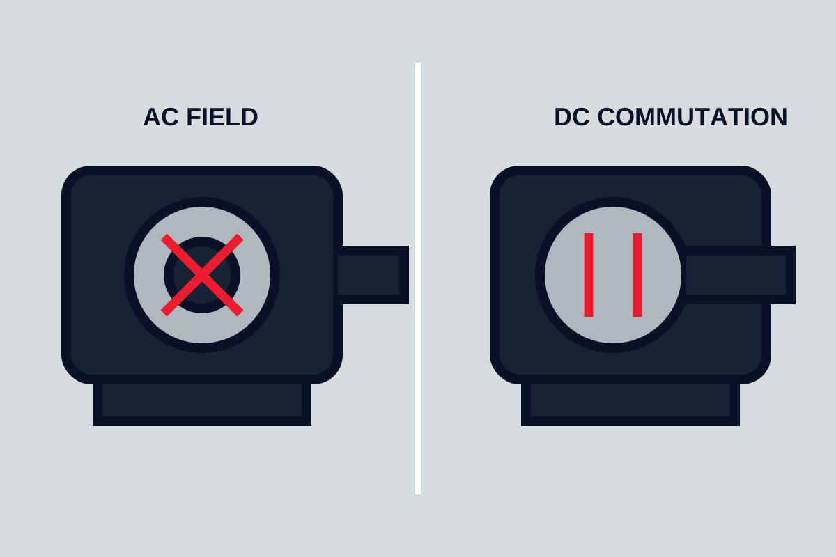
For most new industrial variable-speed duties, an AC induction motor with a suitable drive is the practical default because it combines robust construction, broad availability, and low routine motor maintenance. A DC motor remains relevant where an installed DC system, specialised torque-speed requirement, compact low-voltage supply, or application-specific control architecture justifies brushes, commutation, or a different electronic controller. Compare the complete motor-and-drive system rather than AC and DC labels alone.
Core differences
| Decision factor | AC motor system | DC motor system |
|---|---|---|
| Supply and control | Fixed-frequency supply or variable-frequency drive | DC supply or electronic DC controller |
| Common industrial construction | Squirrel-cage induction motor | Brushed DC, brushless DC, or permanent-magnet variants |
| Mechanical commutation | Not required in induction motor | Required in brushed DC; electronic in brushless designs |
| Routine maintenance | Bearings, cooling, terminals, insulation, driven system | Same basics plus brushes and commutator in brushed designs |
| Variable speed | Excellent with a correctly selected drive | Straightforward with suitable controller; architecture dependent |
| Low-speed cooling | May need separately powered cooling | Also must be checked; brushed and permanent-magnet designs differ |
| Regeneration and braking | Drive and system must support it | Controller and system must support it |
“DC motor” is not one technology. A brushed motor, brushless DC motor, and permanent-magnet synchronous motor can share a DC bus yet have different windings, controllers, feedback, and maintenance. Define the actual architecture.
How AC motors produce torque
An induction motor’s stator creates a rotating magnetic field. Current induced in the rotor produces torque as the rotor runs slightly below synchronous field speed. On fixed-frequency supply, speed is mainly set by supply frequency, pole count, and slip under load.
A variable-frequency drive changes the electrical frequency and voltage supplied to the motor. Modern control can provide good speed and torque performance across a broad range, but the motor, drive, cable, cooling, and protection must be selected together. Low-speed continuous torque can overheat a self-cooled motor because its shaft-mounted fan turns slowly.
Synchronous and permanent-magnet AC designs use a rotor field that follows the stator field without normal induction slip. They may offer different efficiency or power density, but require compatible control and should not be grouped blindly with standard induction motors.
How DC motors produce torque
In a brushed DC motor, current flows through brushes and a commutator to rotor windings. Mechanical commutation switches current as the rotor turns so torque continues in the required direction. Speed responds to applied voltage and torque to current within the motor’s limits, which historically made DC drives attractive for adjustable-speed machinery.
Brushes wear and the commutator requires inspection. Dust, arcing, contamination, vibration, current density, and access influence maintenance. Brush replacement intervals cannot be assumed without the actual duty and construction.
Brushless DC systems use electronic commutation and permanent magnets. They remove brush wear but depend on a compatible controller and rotor-position method. In industrial procurement, verify whether a product called BLDC is actually intended for the supply, control network, enclosure, duty, and service support required.
Starting torque and acceleration
Direct starting of an induction motor can create substantial current and mechanical acceleration. The supply, starter, motor, coupling, gearbox, driven load, and process must tolerate it. Reduced-voltage starting or a drive can control acceleration, but the motor must still produce enough torque throughout the speed ramp.
DC systems can provide strong controlled torque from low speed, subject to current, commutation, thermal, and controller limits. A claimed torque value is not enough; request the continuous and short-duration torque-speed envelope and the conditions behind it.
For either system, define load inertia, breakaway torque, friction, process torque versus speed, starts per hour, reversals, acceleration time, and emergency-stop behaviour. Repeated acceleration can dominate heating even when steady load is modest.
Speed range and control quality
An AC drive can regulate speed with open-loop or feedback control. Required accuracy, low-speed torque, load disturbance, and positioning determine whether an encoder or other feedback is needed. Operation above base speed may be possible, but available torque, rotor stress, bearing speed, noise, and driven-equipment limits must be checked.
Brushed DC control can be simple where supply and duty are modest. Precision and dynamic response still depend on feedback, controller bandwidth, current limits, and mechanical system. Brushless systems require electronic commutation and may provide excellent speed or position control when correctly integrated.
Avoid specifying an extreme speed range without defining continuous torque at each end. Cooling and lubrication often limit the mechanically possible range before control accuracy does.
Efficiency and power quality
Efficiency belongs to the operating point and complete system. Compare motor, drive or controller, cooling, transformer or rectifier where present, gearbox, and mechanical load. A high-efficiency motor running far from its intended load or driving a throttled process may not minimise system energy.
Drives affect input harmonics, power factor behaviour, electromagnetic compatibility, motor insulation stress, and bearing-current risk. The electrical design should address cable length, grounding, shielding, filters, and protective devices according to the installation. Do not claim energy savings without a measured duty profile and baseline.
Maintenance and reliability
AC induction motors avoid brushes and commutators. Routine work focuses on bearings, lubrication where applicable, cooling passages, fan, terminals, insulation condition, alignment, vibration, and environmental ingress. The drive adds electronics, cooling fans or capacitors, firmware, and spare-unit considerations.
Brushed DC motors add brush gear and commutator surfaces. Maintenance access must allow safe inspection and replacement. Brush dust can contaminate the enclosure. Incorrect brush grade, spring pressure, commutator condition, or load can create arcing and wear.
Brushless systems reduce motor wear items but increase dependence on the controller, feedback devices, magnets, and proprietary interfaces. Availability of replacement electronics may determine lifecycle risk.
Installation and environment
Specify voltage, frequency or DC bus, phase, duty, enclosure, ambient temperature, altitude where relevant, moisture, dust, washdown, corrosive atmosphere, hazardous location, and cooling method. Confirm mounting, shaft, flange, terminal orientation, bearings, external loads, and allowable vibration.
Drive-fed motors may need attention to insulation, cable, common-mode voltage, and bearing currents. DC motors with brush arcing may be unsuitable in environments where ignition risk or contamination cannot be controlled. Application-specific certification must be verified rather than assumed.
When to choose each system
Choose an AC induction motor and drive when:
- the project needs a robust, widely serviceable industrial solution;
- variable speed, controlled acceleration, or process integration is required;
- motor maintenance should avoid brushes;
- the motor and drive can be sized for low-speed cooling and dynamic duty.
Choose a brushed DC system when:
- existing machinery and controls make like-for-like support the lowest-risk path;
- the application has a defined low-voltage DC supply or specialised torque-speed need;
- brush and commutator maintenance is accessible and acceptable;
- a modern AC or brushless conversion has been evaluated but is not justified.
Choose a brushless or permanent-magnet system when its power density, control, or efficiency benefits are supported by the complete duty and lifecycle plan—not simply because it carries a newer technology label.
Final motor specification checklist
- continuous and peak torque versus speed, load inertia, starts, reversals, and braking;
- supply characteristics, controller, feedback, communications, and safe failure behaviour;
- speed range, accuracy, low-speed cooling, overload duration, and thermal monitoring;
- enclosure, ambient, ingress, hazardous conditions, mounting, shaft, and external loads;
- drive cable, grounding, filtering, insulation, bearing-current mitigation, and EMC needs;
- maintenance access, brushes where applicable, bearings, cooling, spares, and controller support;
- drawings, motor and drive data, test records, settings, and commissioning checks.
The motor choice should follow the machine duty. If the load and control requirements are not defined, selecting AC or DC first simply moves uncertainty into the drive, cooling, and maintenance design.
Speed and torque
An induction motor on fixed-frequency supply runs near a speed set by frequency and pole count. A drive varies frequency and voltage for controlled speed and torque. Brushed DC motors provide straightforward torque control but require commutator and brush maintenance.
Duty and environment
Check starting torque, overload duration, low-speed cooling, enclosure, insulation and hazardous-area requirements. Repeated starts or regenerative braking can heat the motor and drive even when average mechanical load seems modest.
Compare the whole system
Include drive losses, harmonic mitigation, feedback devices, cables and controls. A robust motor with readily available bearings and service support can deliver lower lifecycle risk than a nominally more efficient but specialised package.