

Both ball valves and butterfly valves can provide quarter-turn isolation, but neither is automatically the better choice. Select the offered valve configuration against the required shutoff criterion, differential pressure, pressure-temperature envelope, fluid properties, line size, actuator duty, installation space, and service access. A valve family name is not a performance guarantee.
Start With the Isolation Duty and Leakage Requirement
Define what the valve must do before comparing body shapes or initial cost. A valve used for routine on-off service may have a different requirement from an emergency shutdown valve, a maintenance isolation point, or a valve that will also be asked to regulate flow.
Collect the line number, nominal size, design pressure, normal and maximum operating pressure, temperature range, fluid composition, solids content, and expected cycle frequency. The piping and instrumentation diagram (P&ID), line list, and valve data sheet should also establish whether the valve normally operates open or closed, its required fail position, and whether flow direction is fixed.
The required shutoff performance needs equally precise language. “Tight shutoff” is not sufficient for purchasing or acceptance unless the project specification defines the test medium, test pressure, permitted leakage, hold period, direction of pressure, and applicable test procedure. A supplier statement that a valve is “bubble-tight” should be treated as a claim for a particular seat design and test condition, not as a general property of all ball or butterfly valves.
For positive isolation during maintenance, confirm the plant’s isolation philosophy. A closed process valve may reduce flow but may not by itself satisfy a requirement for physical separation, double block and bleed, blinding, locking, draining, or verification of zero stored pressure. The final isolation arrangement must be decided under the site’s safety procedures and applicable engineering requirements.
Compare the Flow Path and Open-Position Pressure Drop
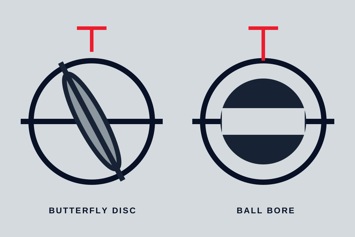
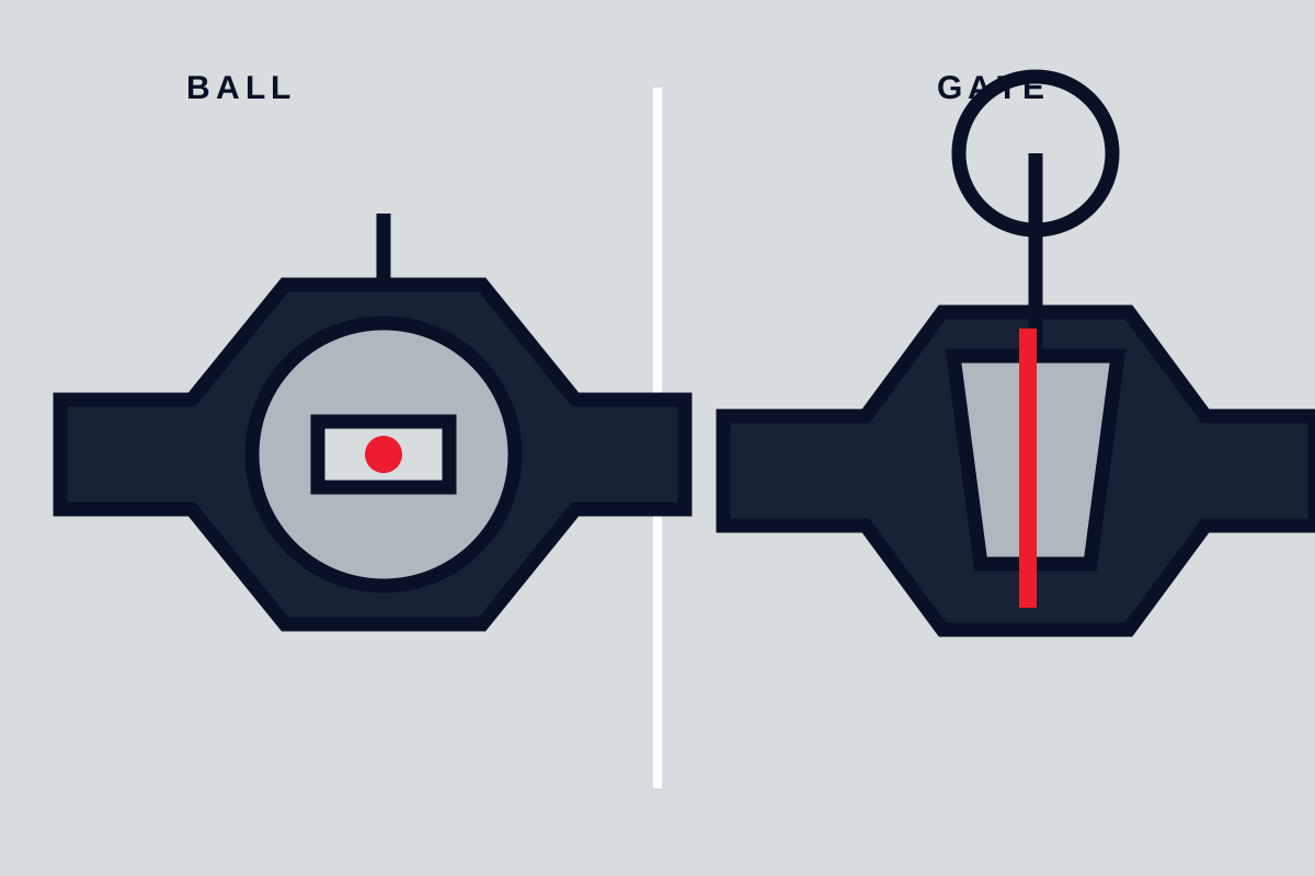
The main mechanical difference is the flow path. A ball valve closes by rotating a drilled ball. In an appropriately sized full-port ball valve, the bore can closely match the connecting pipe bore when open. A butterfly valve closes by rotating a disc through the pipe bore, leaving its disc and shaft within the flow path even in the fully open position.
That difference can matter in several ways:
- Pressure loss: A full-port ball valve may offer a lower restriction than a butterfly valve of the same nominal size, but this must be verified from model-specific flow-coefficient or pressure-loss data. Reduced-port ball valves can introduce a significant restriction.
- Pigging and cleaning: A clear bore may be necessary where pigs, cleaning tools, or inspection devices must pass through the line. Confirm minimum internal diameter, protrusions, seat geometry, and permitted pig type with the valve manufacturer and pipeline designer.
- Solids and deposits: Fibers, particles, scale, sticky products, or crystallizing media can interact with a butterfly disc, seat, ball cavity, or other internal geometry. Fluid characterization and operating history are more useful than a blanket rule that one valve type handles solids better.
- Flow disturbance: The disc and shaft of a butterfly valve create a permanent obstruction and may affect downstream flow conditions. Review the piping layout where flow measurement, pumps, control valves, or other equipment is sensitive to velocity profile or turbulence.
Do not calculate pressure drop from nominal size alone. Obtain the published flow coefficient for the exact valve style, size, bore, disc geometry, and opening position. If the valve will ever operate partially open, use data applicable to that position rather than full-open data.
Match Pressure, Temperature, Fluid Chemistry, and Seat Materials
Ball and butterfly valves are available in many body designs, materials, end connections, and seat arrangements. Neither family has one universal pressure or temperature limit. The usable envelope depends on the exact combination of body material, pressure class, wall thickness, flange or end connection, stem sealing system, seat design, and operating duty.
Start with the complete process envelope:
- Design and operating pressure
- Minimum, normal, and maximum operating temperature
- Maximum differential pressure across the closed valve
- Pressure surges, vacuum conditions, and rapid depressurization
- Fluid chemistry, concentration, contaminants, and cleaning chemicals
- External environment, including corrosion, fire exposure, weather, and hazardous-area requirements where applicable
Seat material is often central to the selection. Resilient polymer or elastomer seats may support low operating torque and good shutoff in compatible service, but their usable temperature, chemical resistance, permeation behavior, and resistance to extrusion vary by compound and construction. Metal-seated or specially engineered sealing arrangements can suit more demanding temperature or pressure conditions, but their leakage performance, torque, wear behavior, and required surface condition must be assessed for the specific design.
Check compatibility for every wetted and sealing component, not only the valve body. This includes the ball or disc, seat, stem, packing or stem seals, bearings, gaskets, coatings, and any elastomeric O-rings. A corrosion-resistant body does not make an unsuitable seat or stem seal compatible with the process fluid.
Pressure-temperature ratings must come from the manufacturer’s documentation for the quoted model and material combination. Confirm whether the stated rating applies to the required end connection, seat material, fluid service, and temperature. Also ask whether the valve has flow-direction limitations under the required differential pressure.
Evaluate Shutoff Behavior, Flow Direction, and Actuation Torque
Both valve types rotate through approximately 90 degrees, but the forces acting during operation differ by design. A ball valve rotates a ball against its seats; a butterfly valve rotates a disc through the fluid stream and into or away from its seat. In both cases, actual operating torque can change with differential pressure, temperature, seat friction, deposits, fluid properties, cycle history, and valve orientation.
Actuator selection must therefore be based on the manufacturer’s torque data for the exact valve. Request breakaway, running, and seating or unseating torque values at the required differential pressure and throughout the expected temperature range. Do not size an actuator from nominal valve diameter alone.
For pneumatic actuation, verify output torque across the available instrument-air pressure range, including the minimum pressure expected during a plant upset. For electric actuators, verify output torque at the actual supply voltage, ambient temperature, duty cycle, and required stroke time. Hydraulic actuators require the same check against available pressure and return conditions.
The actuator package also needs to meet the control requirement:
- Required fail-open, fail-closed, or fail-in-place action
- Emergency shutdown stroke time
- Manual override arrangement and accessibility
- Position indication and limit-switch requirements
- Partial-stroke testing, where specified
- Hazardous-area classification and electrical enclosure requirements
- Mounting interface, coupling, and allowance for stem movement where relevant
Flow direction should be checked even where a valve is described as bidirectional. The stated shutoff performance may differ by direction, especially at higher differential pressure or with particular seat arrangements. Install flow-direction markings as specified by the manufacturer, and do not reverse a unidirectional design without written confirmation that it remains suitable.
Account for Line Size, Weight, Space, and End Connections
Butterfly valves are often considered where larger pipe diameters make installation mass, face-to-face length, and actuator envelope important. Wafer, lugged, and double-flanged butterfly constructions can offer different installation and maintenance characteristics. However, compactness is not a substitute for checking the actual general arrangement drawing.
Ball valves can range from compact small-bore designs to large trunnion-mounted, top-entry, or fully welded valves with substantial support and lifting requirements. A full-port configuration, pressure class, extended stem, gearbox, or powered actuator can materially change dimensions and mass.
Before ordering, compare certified or manufacturer-issued drawings for:
- Face-to-face or end-to-end dimension
- Body mass and actuator mass
- Flange drilling, flange rating, gasket type, and bolting requirements
- Stem clearance and handwheel, lever, gearbox, or actuator envelope
- Support points, lifting lugs, and center-of-gravity information where available
- Clearance for removal, maintenance, and operation
Review the adjacent piping geometry too. Nearby elbows, reducers, supports, insulation, platforms, and cable routes may limit actuator access or prevent removal of a valve body. Large valves and actuator assemblies may require independent piping or structural support; do not assume pipe flanges are intended to carry the full operating and maintenance load.
Plan Maintenance Around Seats, Seals, Cavities, and Access
Maintainability depends more on construction than on the valve family alone. A valve may have replaceable seats, accessible stem packing, a cartridge-style seal system, or a body design that requires full removal from the line for service. These features should be confirmed from the installation, operation, and maintenance manual and the parts drawing for the offered model.
For ball valves, maintenance questions can include seat replacement method, cavity drainage, body-bolt access, stem-seal access, and whether trapped fluid can remain in the body cavity when the valve is closed. The relevance of cavity management depends on the fluid and process temperature. Expanding liquids, hazardous chemicals, polymerizing products, or contaminated fluids can create service-specific concerns that must be addressed by the valve design and operating procedure.
For butterfly valves, review disc-to-seat contact, liner or seat retention, shaft seals, bearings, disc edge condition, and the effect of abrasive solids or repeated cycling. A resilient-seated butterfly valve may be maintainable in one service but unsuitable for in-line repair under another flange arrangement or piping constraint.
Maintenance planning should identify the required spare parts, including seats, seals, bearings, packing, fasteners, and actuator components. Ask whether the manufacturer recommends a service kit for the anticipated duty and whether special tools are needed.
Before any maintenance, isolate the line under the plant’s approved procedure, lock out relevant energy sources, depressurize, drain, flush, and verify that hazardous pressure, temperature, chemical exposure, and actuator movement have been controlled. Follow the manufacturer’s instructions for disassembly, lifting, torqueing, and reassembly. A generic valve procedure cannot replace site-specific process safety requirements.
Use a Service-Based Selection and Quotation Check
A practical selection starts with the service rather than the valve name. A full-port ball valve may be a strong candidate where clear passage, low restriction, or pigging compatibility is required. A butterfly valve may be a practical candidate where installation envelope, mass, and large-diameter layout are decisive. Either can be unsuitable if its quoted seat, pressure-temperature rating, shutoff direction, torque requirement, or material selection does not match the duty.
Use a comparison sheet that requires the supplier to respond against the requested configuration, not against a catalog family. At minimum, include:
| Selection item | What to confirm |
|---|---|
| Function | Isolation only, emergency shutdown, throttling, or combined duty |
| Process conditions | Fluid, solids, design pressure, operating pressure, temperature range, and differential pressure |
| Shutoff requirement | Test medium, pressure, direction, allowable leakage, and acceptance criterion |
| Construction | Valve model, bore type, body style, end connection, seat design, and stem sealing arrangement |
| Materials | Body, trim, ball or disc, seat, seals, packing, bearings, and coatings |
| Hydraulic effect | Full-open flow coefficient or pressure-loss data for the quoted size and design |
| Actuation | Torque basis, actuator output, fail action, stroke time, controls, and manual override |
| Installation | Drawings, face-to-face length, mass, supports, access, and flange compatibility |
| Documentation | Data sheet, general arrangement, material documentation where required, test records, and declared deviations |
Treat all deviations as technical decisions. If a supplier proposes a reduced bore, different seat material, alternate end connection, lower actuator torque margin, or a different leakage test basis, document the effect before approval.
Common Questions
Is a ball valve always better for tight industrial isolation?
No. A ball valve can provide strong shutoff performance in many services, but the result depends on the actual seat design, pressure differential, temperature, flow direction, wear condition, test method, and acceptance criterion. A properly selected butterfly valve may also meet the required isolation duty. Specify the leakage requirement and obtain model-specific confirmation.
When is a butterfly valve more practical in a large pipeline?
A butterfly valve can be practical when available spool length, valve mass, lifting capacity, support load, and actuator envelope are important. This is common in larger pipelines, but the proposed design still needs checks for pressure drop, disc clearance, flow conditions, shutoff requirement, materials, and maintenance access.
Can a butterfly valve be used for throttling as well as isolation?
Some butterfly valve designs can be used for throttling, but suitability depends on the disc profile, seat construction, operating angle, pressure differential, fluid behavior, cavitation risk, vibration, and required control performance. Do not assume that an isolation-rated butterfly valve is automatically suitable for continuous modulation. Request flow and torque information across the intended travel range.
What information is needed to size an actuator for a ball or butterfly valve?
Provide the exact valve model, size, seat and seal materials, maximum differential pressure, temperature range, fluid, required cycle rate, fail position, required stroke time, and available pneumatic, electric, or hydraulic supply conditions. The valve manufacturer’s torque data and the actuator manufacturer’s output data must be compared at the relevant operating conditions.
Choose the valve that satisfies the documented duty with the least unresolved assumption. Before release, require model-specific drawings, pressure-temperature limits, material details, shutoff basis, flow data, actuator sizing evidence, and a clear deviation list. Where the service is hazardous, severe, or safety-critical, the final selection should be reviewed by the responsible piping, process, and safety engineers.