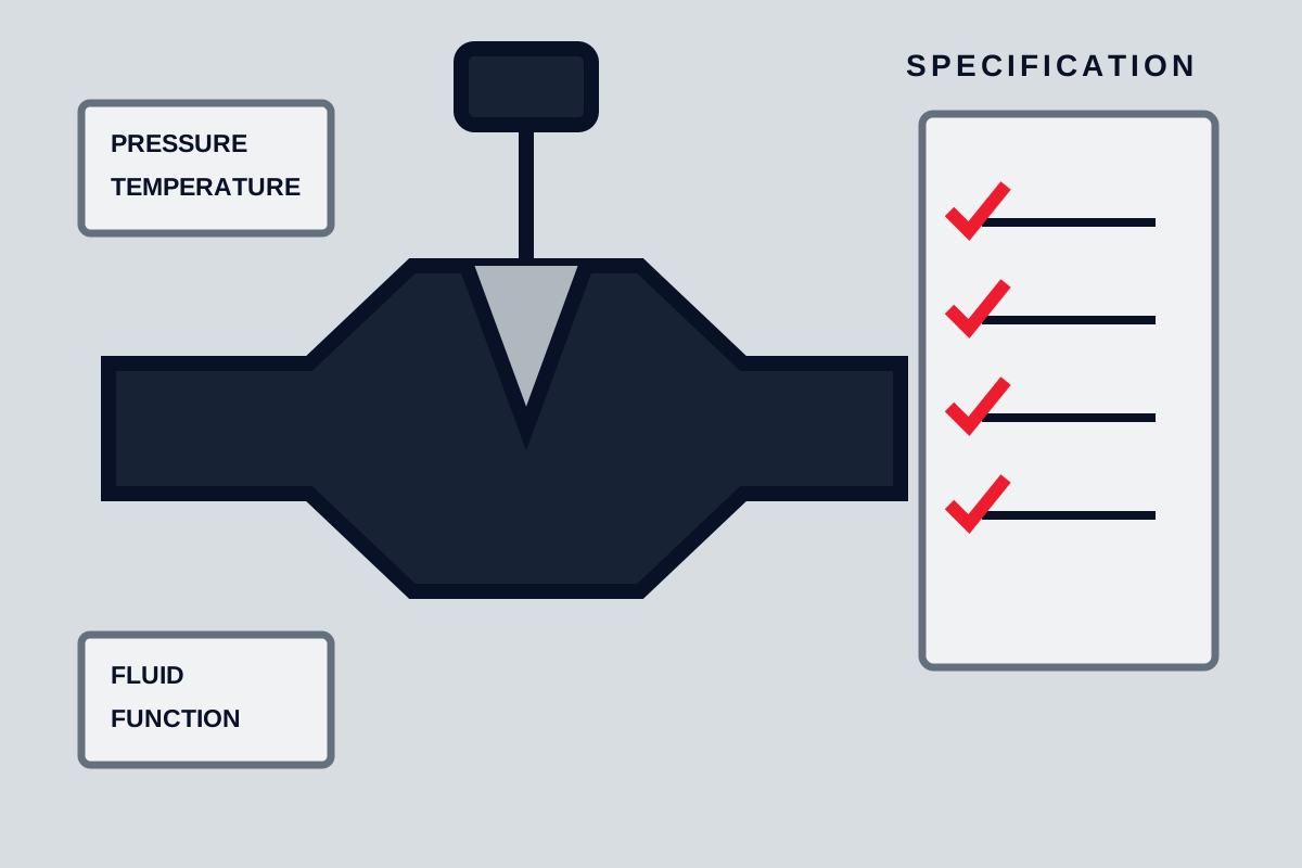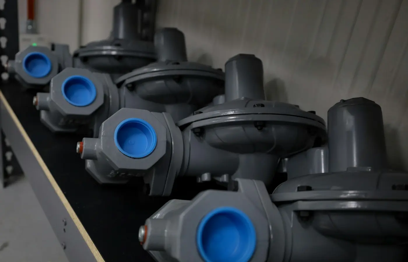
Select industrial valve types first by duty: reliable on-off isolation, continuous flow control, or a combination of both. Then verify the exact valve configuration against fluid conditions, flow range, pressure differential, pressure-temperature rating, shutoff requirement, actuator capability, and maintenance constraints. A ball, butterfly, gate, or globe valve can be appropriate in the right service, but the family name alone does not establish suitability.
Start With the Duty: Isolation, Throttling, or Both
An isolation valve is intended principally to stop or permit flow. It may operate infrequently, such as for equipment maintenance, line isolation, emergency shutdown, or batch transfer. The important questions are usually shutoff integrity, allowable differential pressure during opening and closing, operating torque or thrust, fail position, and the effects of cycling.
A throttling or modulating valve must control flow between fully open and fully closed positions. In this duty, its partially open geometry matters as much as its nominal size. The valve must provide controllable capacity over the required operating range while tolerating the pressure drop, velocity, noise, vibration, and erosion created by restriction.
This distinction is reflected in valve classification guidance. Emerson separates valves into on-off isolation and control-valve applications, while also distinguishing rising-stem designs such as gate and globe valves from quarter-turn designs such as ball and butterfly valves. Its qualification guidance is useful context, but the required duty must still be defined by the project specification and process data.
For a control loop, flow restriction is not an incidental effect. The moving element and flow passage create a restriction that changes fluid velocity and pressure, allowing the process to regulate variables such as level, pressure, or temperature. The ISA control-valve material explains this mechanism and the associated energy loss. That loss can be necessary for control, but it can also create damaging service conditions if the valve and trim are not selected for them.
Before comparing valve families, collect the following inputs:
- Fluid phase, composition, concentration, contaminants, solids, entrained gas, and vapor pressure where relevant.
- Normal, minimum, maximum, and startup flow rates.
- Upstream and downstream pressures at each operating case, not only line design pressure.
- Normal and design temperatures.
- Required shutoff condition and specified seat-leakage acceptance criterion.
- Expected cycling frequency, stroke or response-time requirement, and emergency function.
- Available actuator power, instrument air or electrical supply, required fail action, and hazardous-area constraints.
- Allowable pressure loss when the valve is open and allowable noise or vibration in throttling service.
If one line must both isolate and regulate flow, do not assume one valve will perform both functions satisfactorily. A dedicated control valve plus a separate isolation valve is often easier to specify, maintain, and test. A combined function can be viable only when the selected model is expressly rated and sized for both duties.
Compare the Mechanism and Flow Path of Four Industrial Valve Types
Ball, butterfly, gate, and globe valves alter flow area in different ways. Those mechanisms affect available flow path, behavior in intermediate positions, sealing arrangement, operating force, and maintenance tasks.
Ball valves: rotating bored closure elements
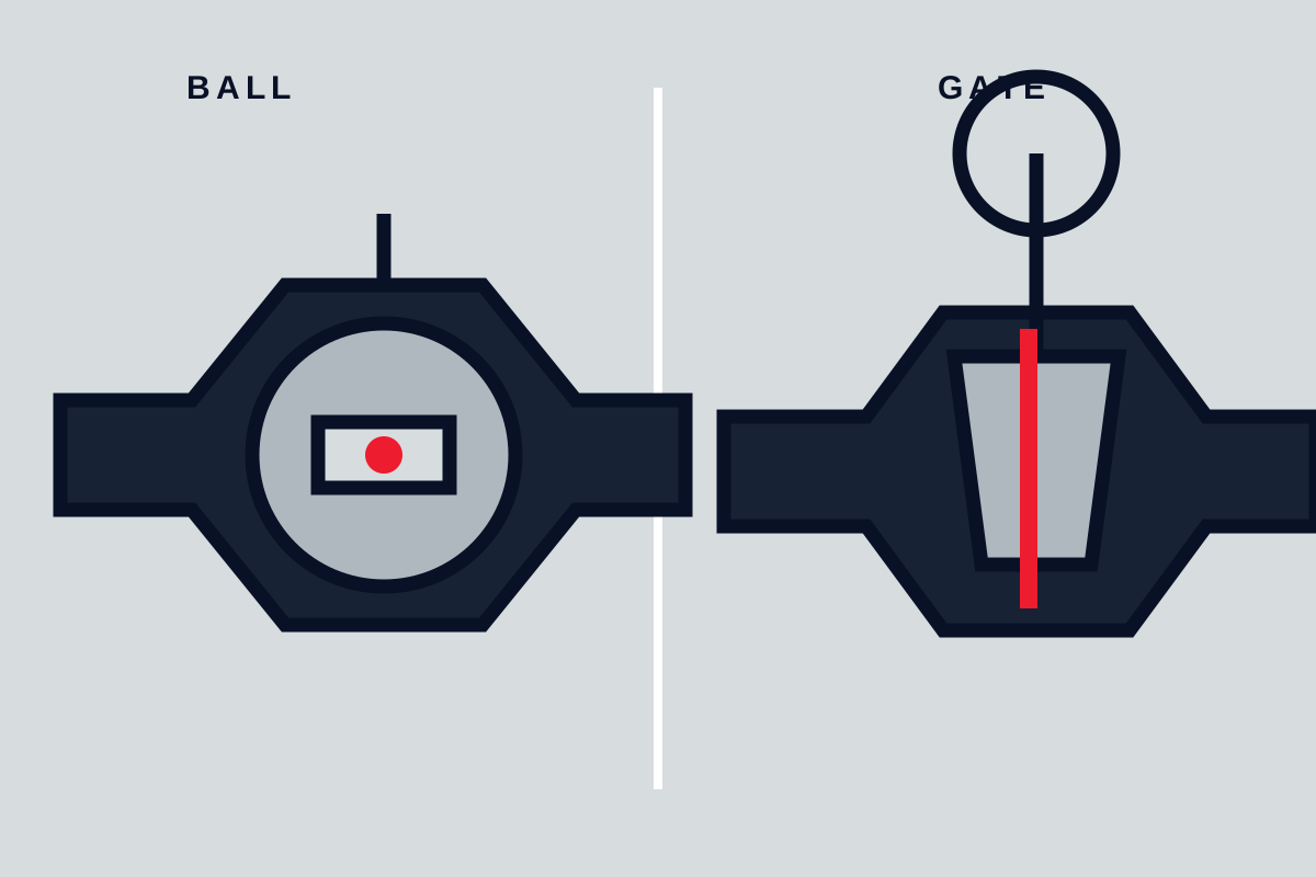
A ball valve uses a drilled ball that rotates within seats. In a typical quarter-turn design, rotation aligns the ball bore with the pipe for open flow and turns the solid portion toward the flow path for closure. Full-port and reduced-port constructions differ materially: a full-port bore may approach the connected pipe bore, while a reduced-port valve has a smaller internal passage. Neither description should be treated as a complete prediction of pressure drop without the manufacturer’s capacity data for the exact size and configuration.
Ball valves are frequently used for isolation because the short rotational movement can suit rapid operation and compact actuation. However, a standard isolation ball valve may be a poor choice for sustained throttling. At partial opening, localized high velocity can damage seats or ball surfaces, create unstable control, or require more actuator torque than expected. Some ball-valve configurations are purpose-designed for control service, but that must be established from the exact trim, permitted control range, pressure differential, and manufacturer documentation.
Butterfly valves: rotating discs in the flow path
A butterfly valve uses a disc that rotates around a shaft. The disc remains in the flow path even at the open position, so the geometry differs substantially from a full-bore ball or fully raised gate. Butterfly designs include concentric, double-offset, and triple-offset arrangements, each with different seat interaction, pressure-temperature limits, torque behavior, and shutoff characteristics.
Butterfly valves can be practical where installation space, valve mass, actuator arrangement, or large nominal line size affect the project. They may serve as isolation valves and, in designs intended for it, as control elements. But disc stability, seat wear, flow direction, cavitation tendency, and torque under differential pressure are configuration-specific issues. A disc intended for isolation should not be presumed suitable for continuous intermediate-position operation.
Gate valves: translating gates out of the flow stream
A gate valve uses a gate or wedge that moves approximately perpendicular to the flow path. When fully open, the closure member is lifted away from the main passage. This mechanism is why gate valves are commonly associated with block or isolation duty.
The common limitation is not that every gate valve must never see an intermediate position; it is that typical gate designs are not selected as general-purpose throttling devices. In partially open service, the flow can impinge on the gate and seats, causing vibration, erosion, or unstable operation. A secondary summary of API RP 615 describes gate valves as common block valves and states that they are typically not recommended for throttling, but it is not a substitute for the applicable official standard or the manufacturer’s instructions. The summary is available here.
Globe valves: translating plugs or discs through a seat
A globe valve generally has a linear-motion closure element that moves relative to one or more ports and seats. Its body geometry routes fluid through an internal passage around the seat region rather than straight through the valve. Emerson’s Control Valve Handbook describes globe-valve arrangements including single-ported, double-ported, angle-style, and three-way forms.
This construction is commonly used for control because it can accommodate trim designed to produce a required flow characteristic. That does not mean every globe valve is automatically a suitable severe-service control valve. The pressure drop, trim design, fluid properties, actuator thrust, rangeability requirement, noise limit, and cavitation or flashing risk remain decisive.
Choose Isolation Valves by Shutoff, Differential Pressure, and Operating Needs
For isolation duty, evaluate the valve in its closed and opening condition as well as its fully open condition. A valve that seals under one pressure direction, temperature, or fluid condition may not provide the same result in reverse flow, high temperature, contaminated service, or after repeated cycles.
Ball valves are often considered for block service where compact quarter-turn operation and a suitable seat arrangement meet the shutoff requirement. Confirm the selected seat material, fire-safe construction where required, antistatic or fugitive-emissions features where specified, and the maximum differential pressure for operation. Soft seats, metal seats, cavity relief arrangements, and body designs can materially alter the service limits.
Gate valves can be appropriate for isolation where a rising-stem, multi-turn arrangement and their installed size are acceptable. Verify the gate design, stem type, seating arrangement, permitted flow direction, stem sealing, and thrust required to operate against the stated differential pressure. They require enough physical clearance for stem travel in rising-stem designs and may impose different maintenance access requirements than quarter-turn valves.
Butterfly valves may be practical for isolation, especially where large diameter, weight, wafer or lug mounting, and rapid actuation are important selection factors. The disc and seat design must be checked against the actual pressure, temperature, flow direction, shutoff criterion, and piping arrangement. A nominal pressure class does not independently prove seat suitability across the full temperature range.
Globe valves can isolate flow, but their internal route may create a higher pressure-loss consequence than a more direct-flow alternative in some services. They may still be justified where control capability, existing piping configuration, or a particular process requirement outweighs that consequence. Compare the actual pressure-drop and capacity data rather than applying a universal ranking.
For any isolation valve, require the quotation and data sheet to state the required leakage criterion and the test method that will be used. Do not specify “zero leakage” unless the purchaser defines what that means, under which test conditions, and for which valve configuration. Also identify whether the valve is required to close under maximum differential pressure, whether it forms part of an emergency shutdown function, and whether lockout or local position indication is required.
Use Globe Valves for Control Only After Sizing the Service
A globe-style control valve is often selected when predictable modulation is needed, but correct sizing is more important than the valve label. The selected valve and trim must provide adequate control at minimum, normal, and maximum required flow without imposing an unacceptable pressure loss or operating too close to its travel limits.
For liquid service, pressure reduction through the valve can cause cavitation if local pressure falls below vapor pressure and then recovers downstream. Flashing occurs when vapor forms and does not recover to liquid downstream. Both conditions can increase noise, vibration, and damage risk. For gas or vapor service, high velocity, aerodynamic noise, vibration, and trim erosion may govern selection.
Request a documented sizing calculation or manufacturer sizing-software output for the ordered configuration. It should identify the fluid, flow range, inlet and outlet pressures, temperature, vapor pressure where applicable, selected trim, valve size, and predicted operating travel. The supplier’s confirmation is useful, but it remains supplier confirmation rather than independent validation.
Check actuator authority as part of the same review. The actuator must position the valve against required process forces, packing friction, and dynamic effects while delivering the specified fail action. Pneumatic, electric, hydraulic, and manual actuator choices bring different response, utility, maintenance, and hazardous-area constraints. Do not select an actuator solely from nominal valve size.
Where Ball, Butterfly, and Gate Valves Become Poor Throttling Choices
Partially open isolation valves can create a restrictive geometry that was not designed for stable control. This is particularly important when the valve is expected to hold a fixed intermediate position for long periods or cycle frequently around that position.
A partially open ball valve may direct high-velocity flow through a narrow and changing opening near the ball and seats. A butterfly valve may experience disc loading, unstable behavior, or increased wear at certain disc angles and flow conditions. A gate valve can expose the gate edge and seats to impingement and vibration when it is not fully open or closed.
These are mechanism-based risks, not universal prohibitions. The Offshore Norge valve handbook notes that regulating duty relies on a controlled pressure drop and that upstream disturbances can alter valve behavior. Its discussion reinforces a practical installation point: evaluate nearby elbows, pumps, reducers, and other disturbances when control performance matters.
Use an isolation-oriented valve for throttling only when the manufacturer explicitly confirms the intended control range, allowable differential pressure, flow direction, fluid limits, torque or thrust requirements, and expected operating conditions. The confirmation should cover the actual seat or trim material, not merely the valve series.
Check Fluid Compatibility, Rating, and Maintenance Access
Valve type does not determine material compatibility. A suitable body material can still be paired with unsuitable seats, packing, stem seals, coatings, or trim. Verify the actual fluid chemistry, concentration, temperature, contaminants, cleaning agents, and expected upset conditions against the manufacturer’s approved compatibility information.
Pressure-temperature limits also belong to the complete configuration. Check the exact body material, pressure class or nominal rating, end connection, seat material, packing arrangement, and temperature range. Thermal cycling, external fire exposure requirements, vacuum conditions, and trapped-fluid expansion may require design features not present in a standard model.
Maintenance should be assessed before purchase, not after installation. Review whether the layout provides access for packing adjustment or replacement where allowed, actuator removal, seal replacement, manual override operation, and lifting. Confirm pipe support requirements and allowable actuator loads from the installation instructions. Before any maintenance, isolate energy sources, control residual pressure, drain or decontaminate the line as required, and follow the manufacturer’s procedures and site safety system.
For abrasive or contaminated fluids, identify likely wear locations: seats, discs, balls, gates, plugs, cages, and downstream piping can all be affected. For viscous fluids, assess whether the valve geometry can trap deposits or create unacceptable pressure loss. For clean fluid, do not assume cleanliness will remain unchanged after startup, corrosion product formation, or upstream equipment upset.
Apply a Valve Selection and Acceptance Rule Before Purchase
Use a documented selection sequence rather than choosing from valve family alone:
- Define whether the primary duty is isolation, continuous control, emergency shutdown, or a verified combined function.
- Eliminate designs outside the stated fluid, pressure-temperature, differential-pressure, contamination, and cycling limits.
- Size remaining candidates for required flow and allowable pressure drop at all relevant operating cases.
- Compare shutoff requirement, control behavior where applicable, operating torque or thrust, actuator and fail action, materials, installation space, and maintenance access.
- Specify the documents and tests needed for acceptance of the ordered configuration.
The purchase package should identify the valve tag, process and design conditions, end connections, body and trim materials, seats and packing, actuator, fail position, required testing, and documentation deliverables. Require the supplier to submit a dimensional drawing, bill of materials, pressure-temperature rating, capacity or flow-coefficient data where applicable, torque or thrust data, material certificates when specified, and applicable test procedures and records.
Accept the valve only against the purchaser’s defined requirements and the submitted configuration documents. Confirm that markings, materials, end connections, actuator action, functional operation, and specified shell and seat tests correspond to the purchase order and applicable verified standards. The final rule is simple: select the valve that demonstrably meets the stated service and acceptance criteria, not the valve type that is merely most familiar.