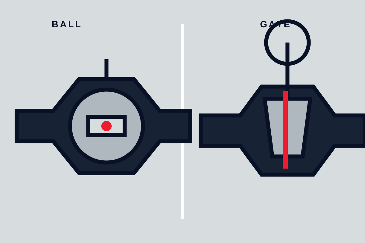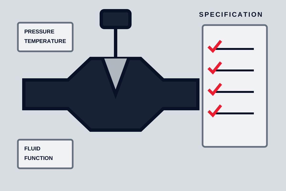
Choose a gate valve for primarily full-open or full-closed isolation when low permanent pressure loss matters. Choose a globe valve when the duty requires deliberate throttling or frequent adjustment and the system can tolerate greater resistance. This rule is only a starting point: the final choice depends on differential pressure, flow range, fluid condition, shutoff criteria, trim design, actuator capacity, orientation, and maintenance access.
Why gate and globe valves behave differently
A gate valve moves a gate across the flow path. In a conventional design, the gate retracts into the bonnet when the valve opens, leaving a comparatively straight passage through the body. The exact bore depends on the design; not every gate valve is full-bore or identical to the adjoining pipe.
A globe valve moves a disc or plug toward and away from a stationary seat. Its internal passage directs the fluid through one or more changes in direction around the seat area. Conventional tee-pattern globe valves consequently impose more resistance than a comparable fully open gate valve. Angle-pattern and Y-pattern globe valves alter that flow path, so pressure-loss data must come from the exact design rather than a generic valve-type comparison.
These geometries affect four practical decisions:
- Isolation: A gate valve is commonly intended to remain fully open or fully closed. A globe valve can also provide isolation, but its acceptable leakage depends on the seat, disc, actuator load, pressure direction, and specified test criteria.
- Throttling: The defined relationship between globe-valve lift and seat opening generally provides more deliberate regulation. Actual control performance still depends on trim profile, sizing, actuator resolution, positioner performance, and process dynamics.
- Pressure loss: A fully open gate normally presents less resistance because the closure member is removed from most of the flow path. Confirm this with the published flow coefficient or resistance data for the selected model and size.
- Wear: A partly open gate places the gate and seat edges in a restricted, high-velocity flow region. Globe-valve trim is arranged for throttling, but it is not immune to erosion, cavitation, flashing, vibration, or wire drawing.
Design variants matter. Wedge, parallel-slide, slab, expanding, and knife gate valves do not have interchangeable operating limits. Globe valves may use different body patterns, guided plugs, contoured trim, soft or metal seats, and balanced or unbalanced discs. The exact manufacturer drawing and data sheet should govern the selection.
Define the valve duty before choosing
Start by naming the required function. Isolation, routine throttling, automatic control, emergency shutdown, and non-return service are different duties even when they occur in the same line.
Collect the following inputs before requesting a quotation:
- Normal valve position and whether intermediate positions are required
- Manual, intermittent, or continuously modulating operation
- Expected operating cycles and required travel time
- Minimum, normal, maximum, startup, shutdown, and credible upset flow cases
- Upstream and downstream pressures, including maximum differential pressure
- Design and operating temperatures
- Fluid composition, phase, viscosity, vapor pressure where relevant, and solids content
- Corrosion, toxicity, flammability, and fugitive-emissions requirements
- Required shutoff performance and the applicable acceptance test
- Available pneumatic pressure, hydraulic pressure, or electrical supply
- Required fail position, position feedback, interlocks, and manual override
- Pipe size and schedule, piping class, end connection, and installation orientation
- Space for the stem, actuator, bonnet removal, lifting, and trim maintenance
Use values from the process data, line list, piping and instrumentation diagram, operating narrative, and project valve data sheet. Normal flow alone is insufficient. A valve that operates acceptably at normal conditions may stall, cavitate, overheat, or fail to shut against a startup or upset differential pressure.
Emergency shutdown service requires additional review. Closing speed can create surge, while fire exposure, stored actuator energy, fail action, diagnostic coverage, and proof-of-closure requirements may determine the design. Neither the words gate valve nor globe valve establish suitability for a safety function.
Select for isolation, throttling, and pressure loss
For a line that normally runs with the valve completely open, a gate valve is often the practical choice. Its relatively unobstructed open flow path can reduce permanent pressure loss, which is important in large lines, gravity systems, pump suction piping, or continuously operating processes where avoidable resistance affects system performance.
Do not assume the nominal pipe size proves low loss. Obtain the flow coefficient or other published resistance data for the exact valve. Calculate pressure drop at the required flow rate using the applicable fluid properties and sizing method. Compare that result with the pressure-loss allowance for the complete piping system, not just the valve.
A standard gate valve should not normally be selected as a control valve unless the manufacturer explicitly approves the design and operating range. At partial opening, localized velocity can erode the gate and seats. The gate may also vibrate or move unpredictably under hydraulic forces. Brief passage through an intermediate position during opening or closing is different from prolonged throttling duty.
Choose a globe valve when the process requires repeatable adjustment over a defined flow range and the extra pressure loss is acceptable. The disc and seat geometry can produce a more useful relationship between travel and flow than a standard gate valve. However, not every globe valve is an accurate control valve. A hand-operated globe valve used for occasional balancing is different from an actuated control valve expected to respond continuously to a process signal.
For modulating service, verify:
- The required flow coefficient at minimum, normal, and maximum flow.
- The percentage of valve travel used at each condition.
- The published inherent flow characteristic of the selected trim.
- The pressure drop allocated to the valve relative to the rest of the system.
- The predicted effects of cavitation, flashing, choked flow, aerodynamic noise, or high velocity where applicable.
- The actuator and positioner resolution needed for stable control.
Oversizing a globe valve can leave normal operation concentrated near the seat, where small stem movements cause large flow changes and velocity may be severe. Selecting by line size alone can therefore produce poor control even when the valve passes the maximum required flow.
Check fluid condition, trim, and flow direction
Fluid condition can override the basic gate-versus-globe rule. Record whether the service is clean liquid, viscous liquid, gas, steam, flashing liquid, two-phase flow, slurry, or liquid carrying entrained solids.
A conventional globe valve used across a high liquid pressure drop may experience cavitation if local pressure falls below the fluid’s vapor pressure and subsequently recovers. If pressure does not recover sufficiently, flashing may continue downstream. Both conditions can cause noise, vibration, erosion, and damage outside the valve. Gas and steam services may develop choked flow or unacceptable aerodynamic noise. These regimes require service-specific sizing and, where limits are approached, review by the valve manufacturer or a qualified engineer.
Solids can collect in body cavities, obstruct seating surfaces, or erode restricted passages. A gate design selected for one slurry service cannot automatically be transferred to another; particle size, concentration, hardness, settling behavior, velocity, and flushing arrangements all matter. Likewise, a standard globe valve should not be assumed suitable for abrasive throttling merely because globe valves are generally associated with flow regulation.
Material selection must cover the wetted and pressure-containing assembly, including:
- Body and bonnet
- Gate, disc, or plug
- Seat rings and hardfacing
- Stem and guides
- Packing, gaskets, and seals
- Fasteners where their environment is relevant
A body material or pressure class does not by itself establish chemical compatibility or pressure-temperature suitability. Confirm the rating of the assembled configuration at the specified temperature, including any soft seats, packing, bellows, or trim components that have lower limits.
Flow direction also requires product-specific confirmation. Some gate valves may operate in either direction under defined conditions, while others have a preferred pressure side or sealing direction. Globe valves commonly have a marked or recommended direction because pressure acting above or below the disc changes operating thrust, shutoff force, stability, and packing exposure. Follow the body arrow and the exact installation instructions rather than applying a universal rule.
Size the valve and actuator for the worst credible load
Valve size and actuator size answer different questions. The valve must pass and regulate the required flow without unacceptable loss or damaging velocity. The actuator must move and seat the closure element against the highest credible mechanical and fluid loads.
For a gate valve, check the thrust or torque required to unseat, travel, and reseat the gate at the specified differential pressure. Include stem friction, packing friction, seat loading, orientation, and any effect of pressure trapped in a body cavity. Long stem travel can influence actuator dimensions and operating time.
For a globe valve, differential pressure acting on an unbalanced disc can create substantial stem thrust. Balanced trim may reduce actuator demand but can introduce additional seals, leakage paths, or operating restrictions. Do not substitute generic torque tables for the manufacturer’s calculation for the exact size, pressure class, trim, flow direction, and pressure case.
An actuator data package should identify:
- Minimum available air or hydraulic supply pressure, or electrical voltage range
- Required thrust or torque in both directions
- Sizing margin and assumptions
- Duty cycle and allowable starts or reversals
- Opening and closing time
- Fail action and stored-energy arrangement
- Ambient temperature and environmental enclosure requirements
- Positioner, solenoid, limit switches, travel stops, and feedback devices
- Manual override and its operating limitations
Fast closure is not automatically desirable. The selected travel time must be checked for pressure surge and process consequences. Conversely, a slow multi-turn valve may be unsuitable where the protective function requires rapid isolation.
Compare maintenance access and likely wear points
Gate-valve inspections commonly focus on gate and seat condition, stem threads, guides, packing, bonnet sealing, and evidence of cavity contamination or corrosion. A valve that has been throttled may require particular attention at the seat edges and gate surfaces.
Globe-valve maintenance commonly focuses on the disc or plug, seat ring, stem, guides, packing, and actuator linkage. Modulating service can concentrate wear on the trim, while poor alignment or guide wear can prevent consistent seating. Replaceable trim can simplify repair, but only if there is enough space to remove the bonnet and lift the internal assembly.
Review the exact maintenance manual and general arrangement drawing before installation. Confirm access for packing adjustment, stem removal, actuator removal, bonnet fasteners, lifting equipment, and any special tools. Also determine whether the valve can be serviced in line or must be removed from the piping.
Before maintenance, isolate the process, verify depressurization, drain or purge hazardous fluid, control thermal and chemical exposure, and lock out electrical, pneumatic, hydraulic, and mechanical stored energy. A closed upstream valve or a pressure indication alone is not proof that the equipment is safe to open. Site procedures and the valve manufacturer’s instructions must define the work method.
Write a purchase specification and acceptance plan
A purchase description should state more than valve type and nominal size. Include:
- Valve design and body pattern
- Nominal size, pressure class, bore, and end connections
- Design pressure and temperature plus all operating cases
- Fluid composition, phase, solids, and corrosion concerns
- Body, bonnet, trim, seat, stem, packing, gasket, and bolting materials
- Required flow coefficient or resistance data and permitted operating range
- Flow direction and installation orientation
- Shutoff and seat-leakage acceptance criteria, including the specified test method
- Actuator type, supply conditions, fail action, travel time, controls, and accessories
- Required drawings, calculations, material documentation, manuals, and spare-parts lists
- Marking, coating, preservation, packaging, and storage requirements
The supplier’s submittal should identify the exact offered configuration. Review its bill of materials, pressure-temperature rating, sectional drawing, flow data, actuator calculation, dimensional drawing, and declared limitations. Certification or country of origin does not replace configuration-specific verification.
A proposed acceptance plan may include document review, visual and dimensional checks, marking verification, material traceability where required, pressure and seat-leakage tests, actuator travel checks, fail-action confirmation, limit-switch settings, and preservation inspection. The applicable project requirements and exact standard editions must be agreed before ordering.
Frequently asked questions
Can a globe valve be used only for isolation?
Yes, a globe valve can be used for on-off isolation if its pressure-temperature rating, shutoff capability, materials, pressure direction, and actuator load meet the service requirements. It may still impose more pressure loss than a suitable fully open gate valve, so isolation capability alone does not settle the choice.
Why should a gate valve not normally be left partly open?
Partial opening places the gate and seat edges in a restricted flow region. High local velocity, turbulence, vibration, and pressure forces can damage sealing surfaces or destabilize the gate. Use it for sustained throttling only when the exact design is expressly approved for that duty.
Which valve has the lower pressure drop at full opening?
A conventional fully open gate valve generally has lower resistance than a comparable conventional globe valve because its flow path is straighter. Verify the difference with exact-model flow data; body pattern, bore, size, trim, and pipe transitions can change the result.
Does flow direction matter for gate and globe valves?
It can matter for both. Flow direction may affect sealing, operating thrust, stability, packing exposure, and cavity pressure. Check the body marking, sectional drawing, and manufacturer instructions for the supplied design.
The bounded selection rule is straightforward: use a gate valve for predominantly full-open or full-closed low-loss isolation, and use a globe valve for intentional throttling or frequent adjustment when its pressure loss is acceptable. Release the purchase order only after the exact valve and actuator are shown to satisfy every credible operating case, shutoff criterion, material limit, flow direction, and maintenance-clearance requirement.
For further technical comparisons, see Gate Valve vs Globe Valve: Engineering Comparison, Gate Valve vs Globe Valve - Isolation vs Control, Globe Valve Guide — Types, Specs, Selection, and Gate Valve vs Globe Valve: How to Choose the Right Pipeline Valve.