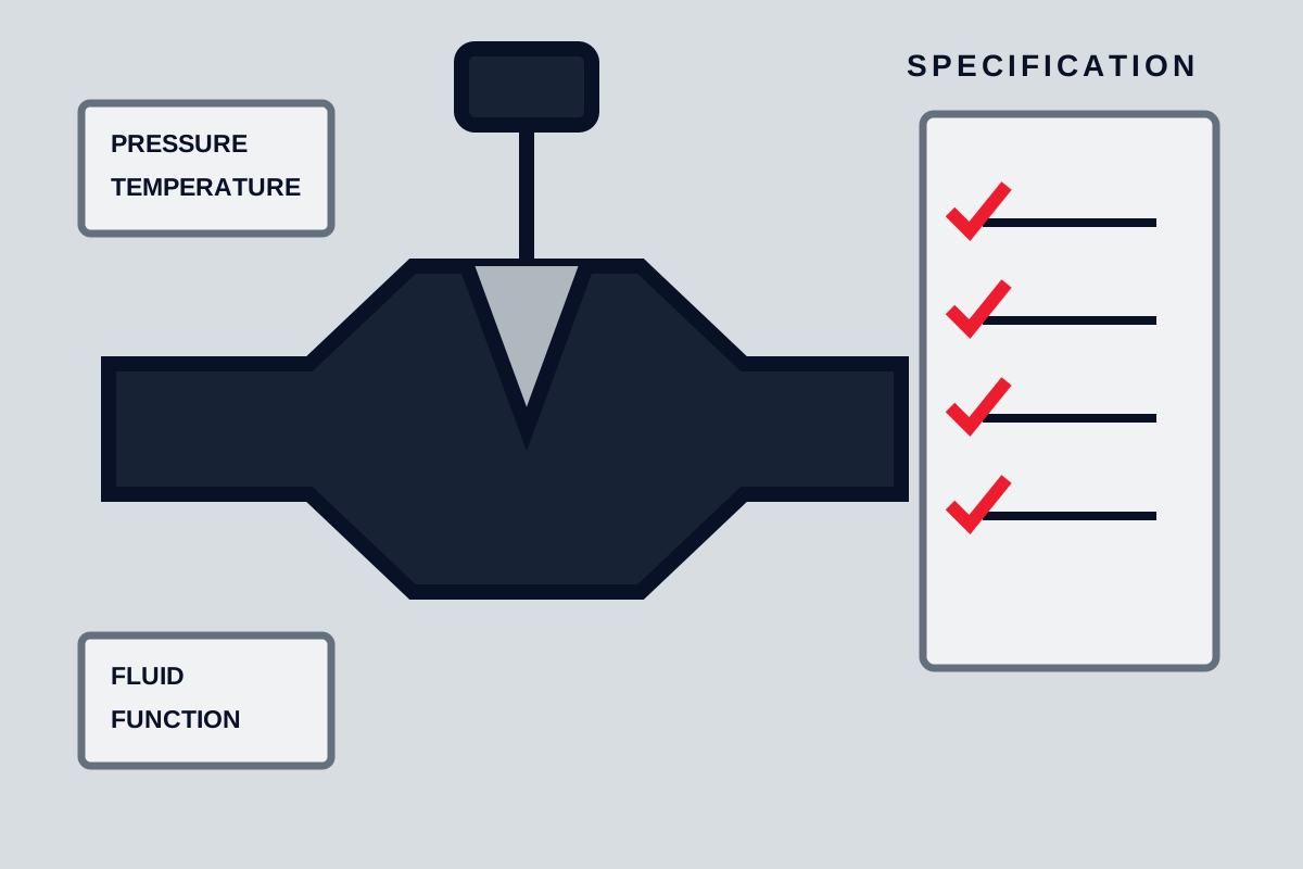
Valve selection begins with function, not nominal size. Isolation, throttling, preventing reverse flow, relieving pressure, diverting flow, and regulating pressure impose different requirements on closure geometry, actuator, seat, and control behaviour. A useful valve specification defines the process envelope and required action clearly enough that suppliers can offer comparable constructions and state deviations.
Define the service envelope
Record normal and limiting pressure and temperature at both sides of the valve. Include start-up, shutdown, cleaning, blocked-line, depressurisation, and standby conditions. The maximum differential across the closed valve may differ from normal line pressure, and the most difficult operating condition may occur during an upset rather than steady flow.
Describe the fluid composition, phase, density, viscosity, vapour behaviour, solids, corrosion, erosion, toxicity, and tendency to crystallise, polymerise, freeze, or deposit. For multiphase service, state expected gas and liquid fractions and whether slugs can occur. Cleaning chemicals and temporary commissioning fluids are also part of the compatibility envelope.
Define how often the valve operates, required stroke time, allowable leakage, flow direction, and expected service life in cycles only when evidence supports such a requirement. A valve that moves once a year has different reliability risks from one cycling every minute.
| Service input | Questions to answer |
|---|---|
| Function | Isolation, modulation, non-return, relief, diversion, or regulation? |
| Pressure | Maximum body pressure and maximum differential during operation? |
| Temperature | Normal, start-up, cleaning, fire exposure, and ambient limits? |
| Fluid | Corrosive, abrasive, viscous, flashing, dirty, toxic, or solids-bearing? |
| Operation | Manual or powered, cycle frequency, speed, fail position, and feedback? |
| Leakage | Which direction, at what differential, and under what test condition? |
Select the valve function first
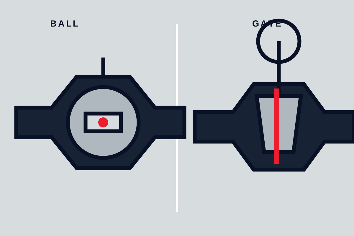
Isolation valves should remain fully open or fully closed and provide the required shutoff after realistic service. Ball, gate, butterfly, plug, diaphragm, and pinch designs can all isolate, but they differ in bore, cavity, seat loading, solids handling, torque, and maintenance.
Control valves must produce predictable flow response and withstand pressure drop at intermediate positions. Globe-style, characterised ball, segmented ball, butterfly, or other control trims may be suitable depending on range, cavitation, flashing, noise, erosion, and actuator needs. Do not use a standard isolation valve for continuous throttling simply because an actuator can stop halfway.
Check valves respond to flow and differential pressure rather than a commanded actuator. Selection depends on minimum flow, reverse velocity, orientation, closing dynamics, pressure surge, and solids. Pressure-relief devices are a separate safety function and require system-level sizing and discharge review.
Compare valve families against the duty
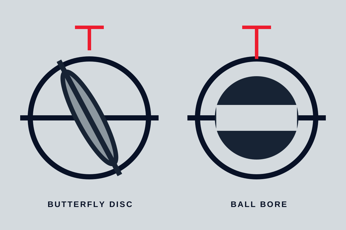
Use valve families to create a shortlist, then compare actual designs. Ball and gate valves both offer low restriction when open but differ in speed, cavity behaviour, and maintenance space. Butterfly and ball valves are both quarter-turn choices, yet a butterfly disc stays in the flow and a full-port ball can provide a clearer bore.
For dirty or abrasive service, review where solids settle and how the closure moves through them. For sanitary or high-purity duties, examine drainability, crevices, surface requirements, cleaning method, and seal compatibility. For vacuum, cryogenic, high-temperature, or hazardous service, do not assume a general-purpose body and seat arrangement can be upgraded by material substitution alone.
The valve should remain stable at the minimum and maximum flow. Oversized control valves may operate near the seat, where response and wear can be poor. Undersized valves may create excessive velocity, pressure loss, noise, or actuator load.
Size for flow and pressure drop
Line size is not automatically valve size. For isolation service, full bore or low restriction may justify matching the pipe. For control service, the required flow characteristic and pressure-drop allocation often determine a smaller trim or valve size with reducers.
Provide flow cases with upstream pressure, downstream pressure, temperature, fluid properties, and required flow. Identify whether liquid can cavitate or flash and whether gas can choke. These conditions require supplier calculations and application review; avoid inventing a single flow coefficient without the underlying cases.
Velocity limits depend on fluid, material, noise, erosion, vibration, and piping design. Treat a generic velocity number as a prompt for project verification, not a universal rule. Examine the highest local velocity through seats and trim, not only average pipe velocity.
Match body, trim, seats, and seals
Body material establishes only part of compatibility. Specify or review the closure element, stem or shaft, seats, guides, bearings, packing, gaskets, fasteners exposed to the process, overlays, and coatings. Temperature affects polymer strength and sealing; pressure and cycling affect deformation and wear.
Corrosion tables are screening tools. Actual suitability can depend on concentration, contaminants, aeration, temperature, flow velocity, and shutdown deposits. If the consequence is significant, require material review against process data and specify the evidence needed for supplied materials.
Soft seats can provide tight isolation but have temperature, chemical, extrusion, and wear limits. Metal seats extend some operating envelopes but do not automatically provide the same leakage performance. Packing selection should consider emissions, friction, adjustment, fire exposure, and maintenance access without claiming compliance to an unverified standard.
Define pressure boundary and connections
State nominal size, connection type, facing or end preparation, pressure class or project design condition, corrosion allowance where applicable, and dimensional standard only after the governing piping specification is confirmed. Pressure-temperature capability belongs to the complete valve assembly, not the body casting alone.
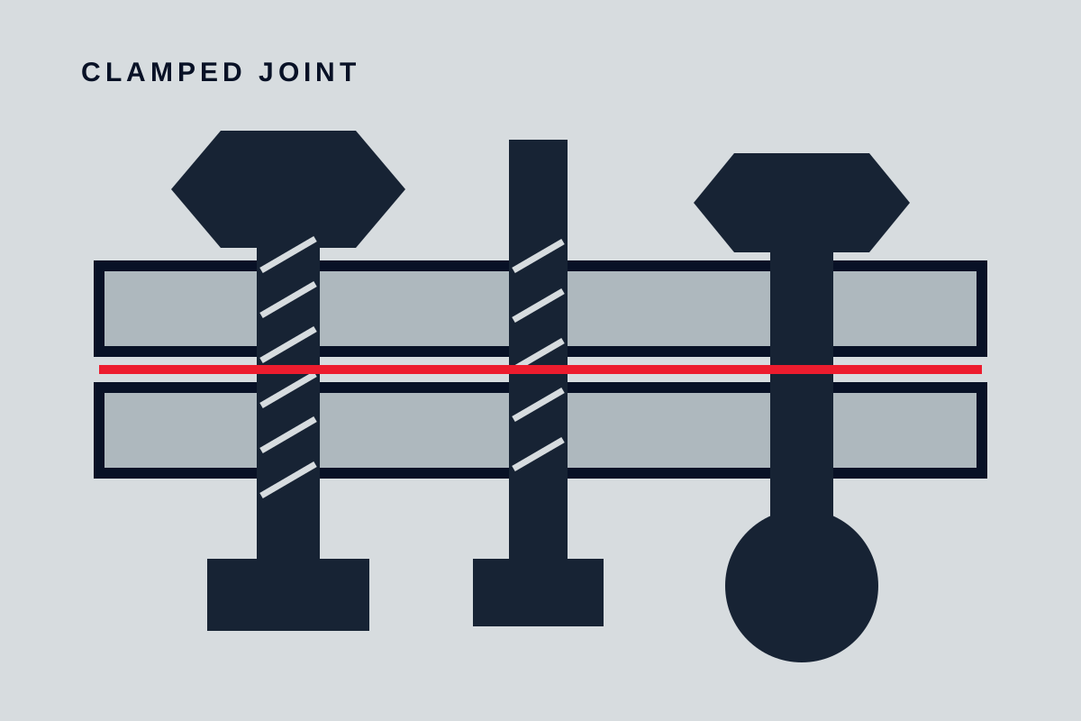
Wafer, lugged, flanged, threaded, socket, and welded connections create different installation and maintenance constraints. Check gasket contact, bolt clearance, pipe bore, disc swing, weld procedure, post-weld treatment, and the ability to remove the valve. Avoid using the valve to pull misaligned pipework together.
Flow direction and orientation may affect sealing, drainage, check-valve dynamics, and actuator support. Require drawings that identify the preferred direction and allowable orientation.
Size the actuator and controls
Actuator selection requires the valve torque or thrust profile, maximum differential, seat friction, packing load, temperature, cycling, and required stroke time. Add project margin transparently; do not select from nominal size alone. Pneumatic supply pressure must use the minimum available value, while electric actuators require supply, duty, enclosure, and control details.
Define the safe failure position based on process consequence. Spring-return or stored-energy action may be appropriate, but the valve must reach the required position under the limiting load. Specify manual override, local indication, remote feedback, limit or torque protection, solenoids, positioners, and diagnostic signals only where they serve a defined need.
Very fast closure can create surge. Very slow closure may fail an emergency requirement. Coordinate operating time with the piping and control study.
Plan maintenance and safe isolation
Ask how seats, packing, seals, bearings, trim, and actuators are inspected or replaced. Confirm whether the valve can be serviced in line, whether the body must be removed, and which lifting or overhead clearances are needed. A low purchase price can be offset by inaccessible maintenance.
Provide drains, vents, cavity relief, and double isolation only when the selected design supports the intended safety function. Never assume a valve is depressurised because its handles appear closed. Maintenance procedures must verify isolation, drain trapped pressure, control hazardous residue, and prevent actuator movement.
Spare parts should be tied to the exact valve and actuator configuration. Generic seat or seal descriptions are insufficient for later replacement.
Prepare a comparable RFQ
Request a completed valve data sheet, general arrangement, sectional drawing, material list, pressure-temperature information, actuator sizing basis, flow data where relevant, and a clear deviation list. For control duty, request the calculation cases and predicted operating openings. For isolation, define the shutoff test direction and condition.
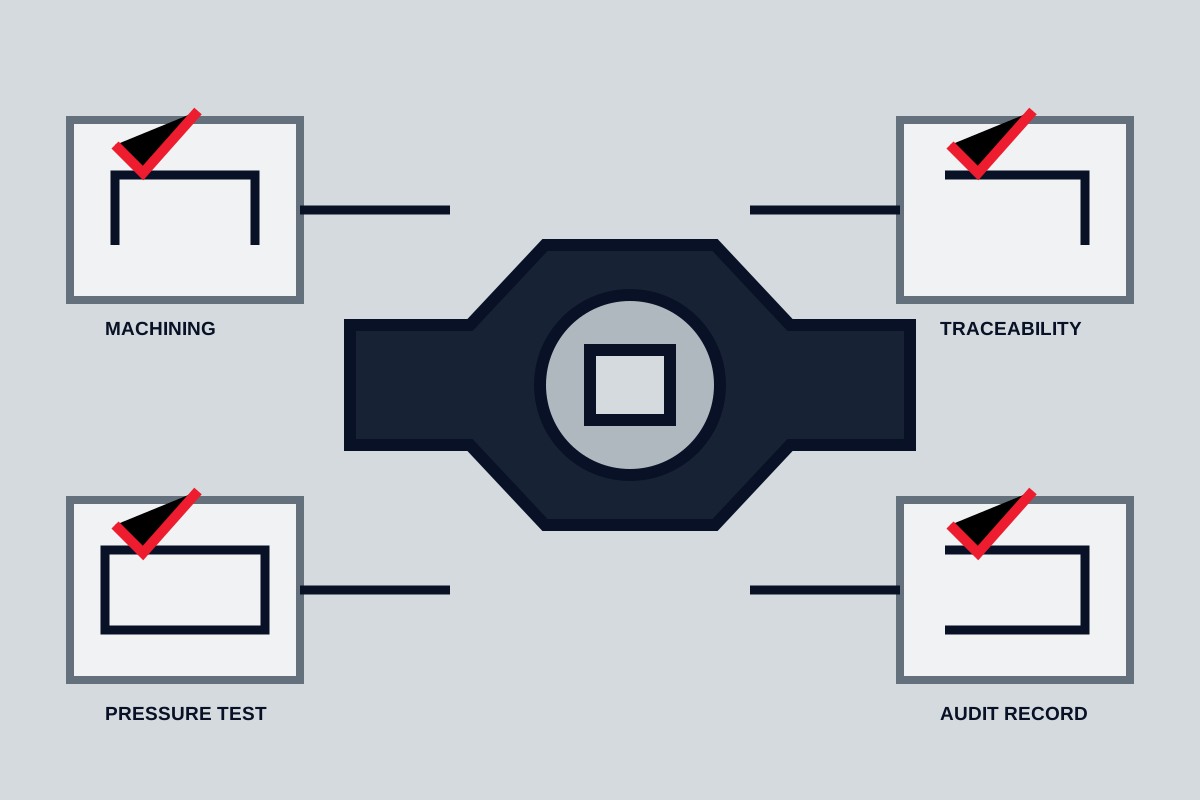
State documentation and inspection requirements before order placement. Depending on risk, these may include material records, dimensional checks, pressure-boundary testing, seat testing, actuator functional testing, coating inspection, nameplate review, and preservation. Do not request certificates without defining what they must trace to.
Common selection mistakes
- selecting only by line size and pressure class;
- using one generic material name for every wetted and pressure-containing part;
- assuming a quarter-turn valve is automatically suitable for control;
- ignoring maximum differential when sizing the actuator;
- failing to define shutoff direction and leakage expectation;
- overlooking trapped cavity pressure, disc clearance, stem travel, or removal space;
- comparing quotations with different accessories, tests, and document scope;
- specifying a standard or certification from memory without checking applicability.
Final valve specification checklist
Before release, confirm the RFQ identifies:
- function, normal position, fail position, operating frequency, and stroke time;
- fluid, solids, phase, chemistry, pressure, temperature, and upset conditions;
- flow cases, pressure drop, bore requirement, and control range where applicable;
- body, trim, seat, seal, packing, gasket, and coating requirements;
- connections, dimensions, orientation, flow direction, drainage, and support;
- manual or powered operation, actuator basis, controls, feedback, and utilities;
- maintenance method, isolation needs, access, lifting, spares, and special tools;
- drawings, calculations, material evidence, testing, inspection, marking, and packing.
A well-selected valve is one whose function remains clear from process data through maintenance. If a supplier cannot show how the offered construction meets the stated envelope, the next step is clarification—not a guess based on valve type alone.
Compare body and trim
Body pressure rating alone is not enough. Seats, seals, stem, closure element and fasteners must tolerate the same service. Check corrosion allowance, erosion velocity, galvanic combinations and whether soft seats retain strength at maximum temperature.
Plan actuation and maintenance
Calculate torque or thrust at the worst differential pressure. Decide the fail position, operating speed, position feedback and manual override. Confirm that the installed orientation and surrounding structure leave space to remove the actuator, bonnet or internal cartridge.