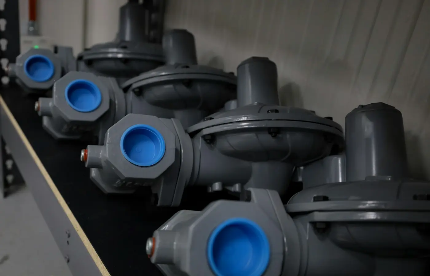
Industrial valve actuator sizing is not a matter of matching a catalog torque number to a valve size. The actuator must operate the exact valve through its complete travel, under the most demanding specified process conditions, with the available utility supply and required failure response. Start with the valve duty and manufacturer operating data; select the actuator only after those inputs are defined.
Start With the Complete Valve Duty, Not the Actuator Catalog
An actuator is part of a valve assembly, not an interchangeable add-on. Its practical functions are to move the closure member, hold the required position, respond to the control signal, and—in some applications—move the valve to a defined position after loss of power or another initiating event. A selection guide from SVF describes the same basic principle: the actuator must provide enough torque or thrust to move the closure member under severe operating conditions and must have suitable controls for the service.
Before requesting a quotation or approving an actuator model, collect the process and mechanical data for the complete valve package:
- Valve tag, manufacturer, model, size, pressure class, end connection, and flow direction.
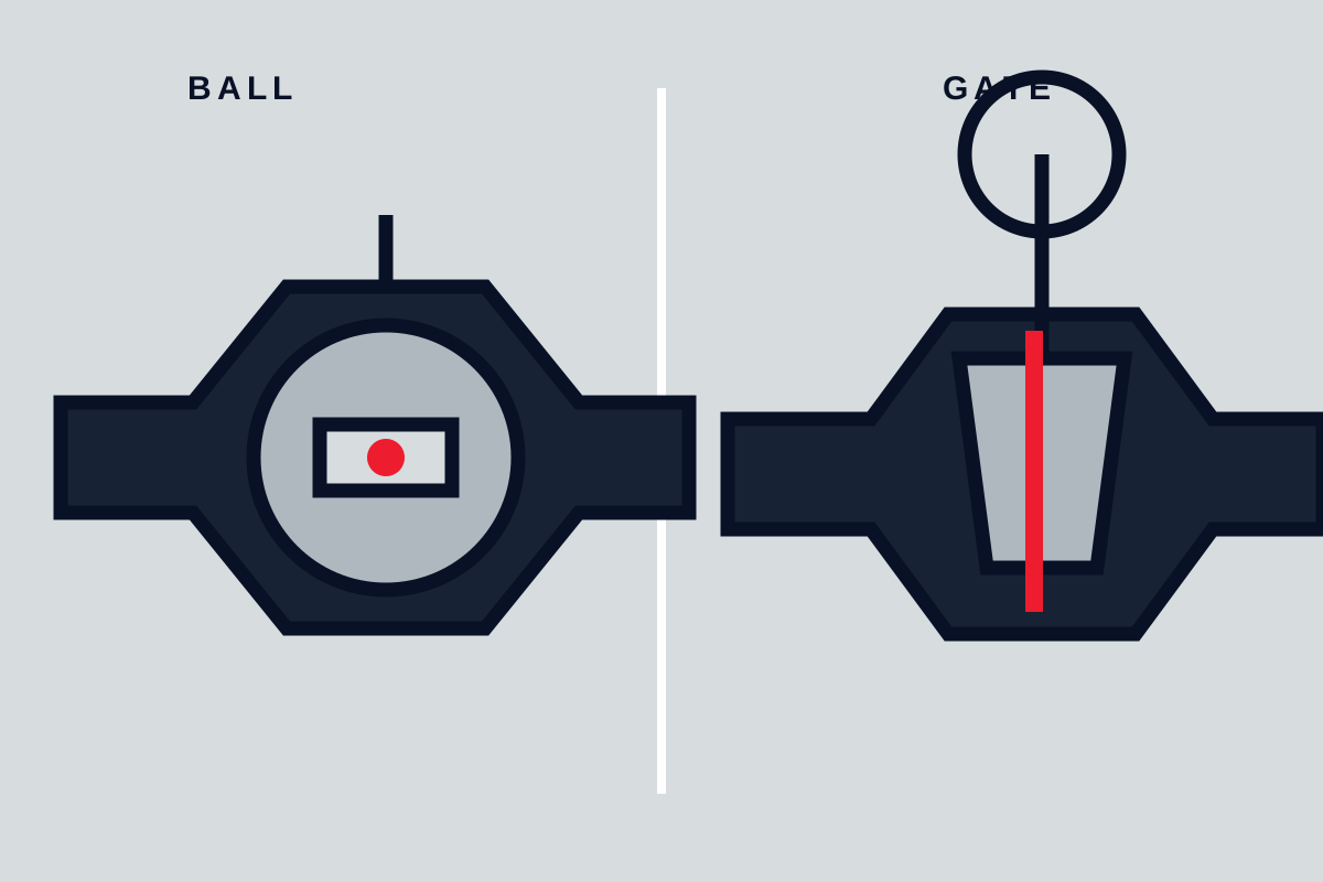
- Valve type: ball, butterfly, plug, gate, globe, diaphragm, knife gate, control valve, damper, or another construction.
- Trim, seat, stem packing, shaft seals, and wetted material configuration.
- Fluid composition, solids content, viscosity, corrosiveness, temperature, and any cleaning or flushing cycle.
- Normal, minimum, maximum, and upset differential pressure across the valve.
- Required action: on-off, throttling, modulating, emergency shutdown, blowdown, or isolation.
- Required stroke time, cycling frequency, expected operating life, and control duty.
- Installation environment, including ambient temperature, washdown, corrosive atmosphere, vibration, altitude, and hazardous-area classification where applicable.
- Available electrical, pneumatic, or hydraulic utility conditions.
- Required fail action, reset philosophy, and manual-operation requirement.
Quarter-turn valves, such as ball, butterfly, and plug valves, are normally evaluated by operating torque. Linear-motion valves, such as globe, gate, and many diaphragm valves, are normally evaluated by actuator thrust or stem force. This distinction is useful, but it does not replace the valve manufacturer’s data. A nominal valve diameter and line pressure alone do not reliably establish operating torque or thrust because sealing geometry, friction, packing load, pressure distribution, and travel position all affect demand.
Ask the valve manufacturer for sizing data for the exact construction being purchased or operated. That request should identify the actual seat, seal, trim, pressure class, fluid, differential pressure, and temperature. A torque figure taken from a similar valve, a different seat material, or a clean-water catalog condition may not represent the required duty.
Match Required Torque or Thrust Across the Full Valve Stroke
The central sizing check is simple in principle: available actuator output must exceed required valve output at every relevant point in travel, under the specified utility condition. In practice, both the valve demand and the actuator output can vary through the stroke.
For a quarter-turn valve, the relevant torque components may include:
- Breakout torque: torque needed to start movement from a static position.
- Running torque: torque needed while the ball, disc, or plug moves through the stroke.
- Seating torque: torque needed to reach the closed sealing position.
- Unseating torque: torque needed to break the valve away from the seated position.
- Dynamic or hydrodynamic torque: process-induced torque that can occur when fluid velocity and pressure forces act on the closure member.
For a linear valve, the equivalent checks can include breakaway thrust, running stem force, packing friction, seating or unseating force, and any load caused by differential pressure. Stem buckling, allowable stem load, and actuator travel must also be checked where applicable.
Do not compare the valve requirement with only the actuator’s maximum advertised output. A pneumatic rack-and-pinion actuator, for example, has an output curve that depends on its configuration and air pressure. A double-acting unit may have different output at the ends and middle of travel. A spring-return actuator has different torque available during the spring stroke and the air stroke. Electric actuator output can depend on gearing, motor duty, voltage, temperature, torque-switch setting, and control arrangement. Hydraulic output depends on available system pressure and the installed cylinder or rotary actuator geometry.
Use the valve manufacturer’s torque-versus-travel curve or certified torque values where available. Then obtain the output curve for the candidate actuator at the actual utility conditions. Compare the curves at the points that matter, not merely at one nominal position.
For ball valves, operating torque is affected by factors including seat material, operating frequency, media type, and line pressure, as noted in Bray’s ball-valve actuator selection guide. That guidance is useful for the valve configurations it covers, but it should not be transferred automatically to another valve design, pressure class, or service fluid.
A sizing sheet should state whether valve torque includes seating, unseating, running, pressure-induced, and frictional effects. If this is unclear, treat the data as incomplete rather than assuming the stated figure covers every condition.
Apply Margin Only After Identifying the Source of Variation
Actuator sizing margin is often discussed as though one universal percentage applies to all valves. It does not. The necessary allowance depends on why operating demand may rise and whether the available actuator output may fall.
Valve demand can increase because of packing friction, seat swelling, seal aging, deposits, corrosion products, lubricant changes, solids accumulation, thermal effects, or changes in differential pressure. A valve that cycles infrequently may develop higher breakout demand than the same valve operating repeatedly in clean service. A modulating valve may experience different loading from an isolation valve that remains stationary for long periods.
Available actuator output can decrease because of low instrument-air pressure, undersized air piping, pressure loss during simultaneous demand, cold ambient conditions, low electrical voltage, motor thermal limits, hydraulic pressure loss, or degraded stored-energy equipment. The available output must be based on the minimum credible utility condition for the required action, not only the nominal supply nameplate value.
The correct process is therefore:
- Identify the variation expected from the valve design, process fluid, environment, and operating history.
- Confirm whether the valve manufacturer has a stated allowance or service-specific recommendation.
- Confirm the actuator output at the limiting utility condition and relevant stroke position.
- Record the adopted margin and the reason for it in the selection calculation or package sizing sheet.
For a replacement on an existing installation, maintenance records can be more valuable than generic rules. Repeated high torque-switch trips, spring failures, sticking after shutdown, slow stroking, air-pressure drops, or leakage may indicate that either the valve duty, actuator selection, or utility system needs reassessment. Increasing actuator size without identifying the source of abnormal demand can overload valve stems, shafts, seats, brackets, or travel stops.
Choose Electric, Pneumatic, or Hydraulic Power From the Available Utilities and Duty
Electric, pneumatic, and hydraulic actuators can all be suitable. The selection should follow the available utility, output requirement, control duty, speed, failure response, environmental conditions, and maintenance capability—not a general preference for one technology.
Electric actuators
Electric actuators are often considered where suitable electrical power is available and where plant controls require direct digital or analog integration. They may be used for on-off isolation, modulating duty, or remote operation, depending on the actuator design and stated duty rating.
Verify supply voltage, frequency, phase, available current, motor starting demand, enclosure, ambient temperature limit, duty cycle, travel time, control signal, torque-switch arrangement, and manual override. If a valve must move during loss of normal power, determine what energy source will perform that movement. Possible arrangements include battery backup, stored mechanical energy, an uninterruptible supply, or a separate emergency power system, but capability is model- and configuration-specific.
Pneumatic actuators
Pneumatic actuators are common where instrument air is available and fast, repeated cycling or spring-return action is required. They may be double acting or spring return. Spring-return designs can move in the spring direction after loss of air, but only if the spring output remains sufficient for the actual emergency valve duty.
Check minimum and maximum air pressure, air quality, dew point, contamination limits, air consumption, pipe size, local receiver capacity if used, solenoid specification, and the pressure available during concurrent plant demand. The actuator may be adequately sized at the compressor discharge pressure yet fail to develop adequate output at the actuator inlet during an emergency stroke.
Hydraulic actuators
Hydraulic actuators can be appropriate where high force or torque is required, where an existing hydraulic power unit is available, or where controlled high-load movement is needed. Their suitability depends on actual pressure, flow capacity, fluid condition, hose and piping arrangement, accumulator design where fitted, temperature range, leakage management, and maintenance resources.
Hydraulic systems can incorporate stored energy and emergency operation, but that result depends on the complete design rather than the word “hydraulic” on the datasheet. Confirm the accumulator, isolation valves, control logic, and pressure available during the specific failure scenario.
General training material from Exal Technology identifies energy supply, operating frequency, torque, failure position, speed, and control requirements as key actuator selection factors. These are useful selection categories, but final suitability requires the exact manufacturer data for the proposed assembly.
Set the Fail Position and Prove It Under the Actual Failure Scenario
Fail-open, fail-close, fail-in-place, and fail-to-position are process decisions. They should originate in the process hazard analysis, shutdown philosophy, cause-and-effect matrix, or equivalent project documentation—not from a generic assumption about the valve type.
Define the initiating event first. “Power failure” may mean loss of local electrical supply, loss of instrument air, loss of hydraulic pressure, loss of control signal, emergency shutdown command, cable failure, or loss of a distributed control system. Each event can produce a different actuator response.
For every critical valve, document:
- Initiating failure or command.
- Required final valve position.
- Required travel time.
- Maximum acceptable delay before movement begins.
- Energy source available after the initiating event.
- Required seating or holding load in the final position.
- Reset behavior after utilities return.
- Local manual-operation requirements.
- Proof-test or functional-test requirements.
A spring-return pneumatic actuator is often suitable where loss of air must cause a defined open or closed movement. However, confirm spring output at the relevant end of travel, not only the pneumatic output during normal operation. A spring-return actuator can be adequate for normal cycling while being inadequate for emergency seating at low temperature, elevated friction, or maximum differential pressure.
Electric actuators are not automatically incapable of fail-safe operation, and pneumatic actuators are not automatically fail-safe. The answer depends on the actuator configuration, energy storage, control logic, utility condition, and required final load. For a critical duty, obtain written manufacturer confirmation that the specified valve-actuator assembly can complete the required movement under the stated failure scenario.
Verify the Mechanical Interface, Controls, and Sizing Sheet Before Release
A technically correct output calculation can still lead to a failed installation if the mechanical interface or controls are mismatched. Review the valve and actuator as one packaged assembly before purchase release.
Mechanical checks
Confirm the shaft, stem, keyway, coupling, mounting flange, bracket, drive sleeve, and travel-stop arrangement. Check the permitted stem thrust, shaft torque, side load, and axial load for the valve and actuator. Confirm that the actuator travel matches the valve travel and that mechanical stops do not force load into valve internals at the end of stroke.
For valves with a handwheel, declutch mechanism, or manual override, verify access, operating direction, clearance, and behavior during loss of power. Manual override arrangements are not a substitute for a defined emergency function unless the operating procedure explicitly permits the required response time and access conditions.
Controls and environment checks
Confirm the solenoid voltage, coil duty, positioner type, feedback signals, limit switches, partial-stroke-test equipment if specified, cable entries, enclosure rating, ambient limits, and hazardous-area documentation required by the project. Do not infer hazardous-area or ingress-protection suitability from a similar actuator family; verify the exact model, enclosure, accessories, and approval marking.
For pneumatic packages, verify air connection size, filter-regulator requirements, tubing or pipe sizing, exhaust arrangement, and whether the stated air consumption applies to the selected spring and cylinder configuration. For electric packages, confirm terminal arrangement, heater requirements, local controls, remote interlocks, and torque-switch settings. For hydraulic systems, confirm pressure rating, flow demand, filtration, accumulator inspection requirements, and emergency circuit arrangement.
Required release documentation
The manufacturer sizing sheet or written selection confirmation should identify the exact valve tag and configuration used for the selection. At minimum, it should state:
- Valve model, size, trim, seat, packing, and pressure class.
- Process fluid, temperature, and normal and maximum differential pressure.
- Valve torque or thrust data and the condition on which it is based.
- Actuator model, configuration, output curve, and applicable utility conditions.
- Adopted allowance or margin and the stated basis for it.
- Fail action, emergency energy source, and required failure condition.
- Stroke time, control accessories, feedback, enclosure, and area-classification requirements.
- Mechanical mounting arrangement and manual override details.
Factory acceptance testing and commissioning should verify the agreed function rather than create undocumented assumptions. A proposed check may include confirming direction of travel, limit-switch operation, control signal response, stroke time, utility pressure or voltage at the actuator, feedback indication, and required fail action. Isolation, depressurization, electrical lockout, guarding, and manufacturer procedures must be applied before any adjustment or functional test.
Common Actuator Sizing Questions
How much torque margin should be used when sizing a valve actuator?
There is no universal percentage that is reliable for every valve. Determine the source of expected variation—such as deposits, packing friction, seat changes, low utility pressure, or temperature—and use the valve and actuator manufacturers’ guidance for the actual service. Document the selected allowance and its basis.
What is the difference between valve torque and actuator torque?
Valve torque is the torque the valve requires to move, hold, seat, or unseat under stated conditions. Actuator torque is the output the actuator can deliver under stated utility and configuration conditions. A suitable selection requires actuator output to exceed valve demand at the relevant positions throughout the stroke.
When should a valve use a spring-return pneumatic actuator?
Consider spring return when the process requires a defined valve movement after loss of air or control power and a pneumatic utility is available. Confirm that the spring stroke supplies adequate torque or thrust at the required travel position, pressure differential, temperature, and emergency condition.
Can an electric actuator provide a fail-safe valve position during power loss?
Some electric actuator packages can provide a defined response through stored energy, backup power, or another designed emergency arrangement. This cannot be assumed from the actuator type alone. Verify the exact emergency module, available stored energy, stroke requirement, valve load, ambient limits, and reset behavior.
Select the actuator only after the valve manufacturer’s torque or thrust data, the actuator output curve, utility limits, fail-position requirements, and mechanical interface have been checked as one system. If the duty includes emergency shutdown, severe process conditions, or uncertain valve friction, require written package confirmation from the responsible valve and actuator manufacturers before release.