Choose hydraulics when high force, controlled load holding, stiffness, and compact actuators dominate. Choose pneumatics when fast repetitive motion, clean point-of-use hardware, simple end-to-end movement, and moderate force are more important. Both can be safe and reliable, but only when the power source, valves, lines, actuator, controls, and failure behaviour are designed as one system.
Core differences
| Decision factor | Hydraulic system | Pneumatic system |
|---|---|---|
| Working medium | Liquid | Compressed gas, usually air |
| Stiffness | Higher because liquid is relatively incompressible | Lower because gas stores compression energy |
| Force density | High | Moderate for practical component sizes |
| Motion | Strong control of heavy loads; valve and feedback design still matter | Fast cycling and simple end positions; compliance affects precision |
| Power source | Pump, reservoir, conditioning, and heat management | Compressor, receiver, drying, filtration, and distribution |
| Leakage consequence | Oil loss, slip, contamination, fire or environmental risk depending on fluid | Energy loss, noise, pressure decay, and contamination entry |
| Energy behaviour | Losses generate heat; variable demand can be managed by power-unit design | Compression and leaks can make central air costly for continuous high demand |
Neither system should be chosen from actuator force alone. Duty cycle, speed, control accuracy, environment, utility availability, maintenance capability, and safe response to hose or power failure are equally important.
How hydraulics transmit power
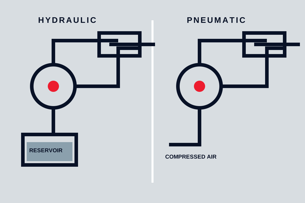
A hydraulic pump creates flow. Resistance to that flow creates pressure, and pressure acting on actuator area produces force. Directional, pressure, and flow-control valves manage movement and protect the system. The reservoir supports deaeration, cooling, and fluid supply, while filters control contamination.
Because liquid compresses relatively little, hydraulic actuators can feel stiff and control heavy loads. Real systems still contain compliance in hoses, trapped gas, seals, structure, and fluid. Air entrainment can make motion spongy and increase heat or noise.
Pressure is not a direct indication of pump health or available flow. A blocked actuator can create high pressure with no useful motion. Specify force and speed cases so pump flow, pressure, actuator area, motor power, valves, and cooling can be evaluated together.
How pneumatics transmit power
A compressor raises air pressure and stores energy in receivers and distribution piping. Point-of-use preparation may filter, regulate, dry, or lubricate the air according to component needs. Directional valves send air to cylinders, rotary actuators, grippers, or air motors; exhaust returns to the surroundings, often through silencers.
Compressed air expands as load changes. That compliance helps absorb shock but makes rigid low-speed positioning more difficult. End cushions, flow controls, shock absorbers, proportional valves, and feedback can improve motion, but a simple cylinder remains best suited to clear end-to-end tasks.
Air quality matters. Water, oil, particles, and pressure drop affect valves and seals. Excessive drying or adding oil without system need can also create maintenance problems. Define the required air condition instead of applying a generic package.
Force, speed, and load holding
Hydraulic cylinders generate high force from relatively small piston area because practical hydraulic pressure is much higher than typical plant air. This makes them suitable for presses, forming, lifting, clamping, and heavy mobile equipment. Force still varies with friction, backpressure, mechanical geometry, and pressure loss.
Pneumatic cylinders are effective for sorting, packaging, stops, doors, light clamping, and high-cycle automation. Their speed can be high, but exhaust flow and cushioning must control end impact. Oversizing a cylinder increases air consumption and stored energy without necessarily improving process control.
Do not rely on trapped fluid or air as the sole means of holding a suspended load. Valve leakage, hose failure, seal leakage, temperature change, and compression can allow movement. Use engineered load-holding, mechanical support, or restraint appropriate to the hazard.
Precision and control
Hydraulic proportional or servo control can regulate force, position, and speed under high load. Performance depends on valve sizing, feedback, contamination control, fluid temperature, structural stiffness, and controller tuning. Low-speed stick-slip and leakage can still limit accuracy.
Pneumatic positioning is affected by compressibility and changing load. Servo-pneumatic systems can achieve useful controlled motion, but they require feedback and careful sizing. For simple automation, fixed stops and end sensors are often more repeatable and maintainable than attempting to stop a basic cylinder mid-stroke.
Define the actual requirement: end-position confirmation, repeatable intermediate positions, controlled force, smooth low speed, synchronisation, or rapid cycling. Each leads to a different circuit.
Energy and heat
Hydraulic losses across valves, pumps, leakage paths, and throttles become heat. A fixed-displacement pump continuously bypassing unused flow can waste power and overheat oil. Variable displacement, unloading, accumulators, or variable-speed power units may improve a variable duty, but selection needs a real load cycle.
Compressed air requires energy to produce, cool, dry, distribute, and regulate. Leaks and excessive pressure increase demand. Using air for continuous blowing or high-force steady work may be inefficient. Measure demand and pressure at the machine rather than assuming the header condition is adequate.
Energy claims require a defined baseline. The correct comparison is total input energy for the required motion and duty, including standby losses, cooling, and air preparation.
Cleanliness, leakage, and environment
Hydraulic leakage can create slip hazards, product contamination, fire risk near ignition sources, and environmental obligations. Hose routing, fittings, seal compatibility, guarding, and inspection are central design tasks. Fluid choice must match temperature, fire risk, materials, and disposal requirements.
Pneumatic leakage is less visible but wastes energy and can allow pressure to decay unexpectedly. Exhaust noise and oil mist may affect workers or products. In dusty or wet locations, poorly arranged exhausts can draw contamination into valves and cylinders.
For clean manufacturing, pneumatics may offer simpler point-of-use cleanliness, but air quality and exhaust must still be managed. Hydraulic systems can also be enclosed and monitored; neither medium guarantees cleanliness by itself.
Safety and stored energy
Both systems store energy. Hydraulic accumulators, raised loads, compressed hoses, pneumatic receivers, and trapped actuator volumes can move after electrical power is removed. Isolation must include releasing or mechanically restraining stored energy and verifying a safe state.
Hose failure can inject hydraulic fluid, release a load, or create whipping. Pneumatic line separation can also whip and create noise or flying debris. Protect lines from abrasion, heat, crushing, and incorrect bend. Use rated components and controlled assembly procedures without substituting generic pressure assumptions for the actual design.
Emergency stopping must consider whether stopping flow creates a safer state or traps a hazardous load. Define what each actuator should do when electrical power, hydraulic pressure, air pressure, or control communication fails.
Maintenance and troubleshooting
Hydraulic reliability depends on fluid cleanliness, correct viscosity, reservoir condition, filters, breathers, cooling, seals, hose condition, and control-valve health. Slow movement may result from pump flow, internal leakage, valve restriction, low fluid, air ingress, or load—not simply low pressure.
Pneumatic maintenance focuses on leaks, filters, dryers, regulators, valve contamination, silencers, tubing, cylinder seals, and pressure drop. A cylinder that lacks force may be undersized, supplied at insufficient pressure, restricted, misaligned, or mechanically overloaded.
Instrument the circuit at points that distinguish causes. Pressure before and after a valve, actuator position, flow, temperature, and cycle time can be more useful than replacing components by trial.
When to choose each system
Choose hydraulics when high force density, heavy-load control, continuous force, or stiff motion justifies the power unit, fluid management, and leakage controls. Choose pneumatics when moderate force, rapid repetitive movement, simple end positions, and existing clean-air utility support a smaller and simpler machine circuit.
Consider electric actuation when the duty needs efficient point-to-point positioning, programmable motion, and no fluid-power infrastructure. The decision should compare the complete lifecycle and safe failure behaviour rather than preserve a familiar technology automatically.
Final decision checklist
- force, speed, stroke, cycle rate, load variation, inertia, and holding requirement;
- position, force, synchronisation, and end-of-stroke control accuracy;
- available electrical, hydraulic, or pneumatic utilities and their real capacity;
- duty-cycle energy, standby loss, heat rejection, air treatment, and cooling;
- leakage, cleanliness, fire, noise, exhaust, environmental, and product risks;
- stored energy, hose failure, suspended load, isolation, and emergency response;
- filtration, fluid or air quality, monitoring, maintenance skills, and spares;
- line routing, pressure loss, actuator mounting, mechanical alignment, and guarding.
Hydraulic and pneumatic systems are architectures, not interchangeable actuator choices. Define the motion and risk first, then select the medium and circuit that can deliver it predictably.
Energy and environment
Compressed air is convenient but energy-intensive when leaks, pressure drops and compressor losses are included. Hydraulic leaks create housekeeping and contamination concerns, while oil temperature and cleanliness directly affect reliability.
Choose around the task
Define force, speed, stroke, cycle rate, positioning, duty and safe failure behaviour. Then compare the complete power unit, valves, conditioning equipment, piping, controls and maintenance capability rather than only the actuator.