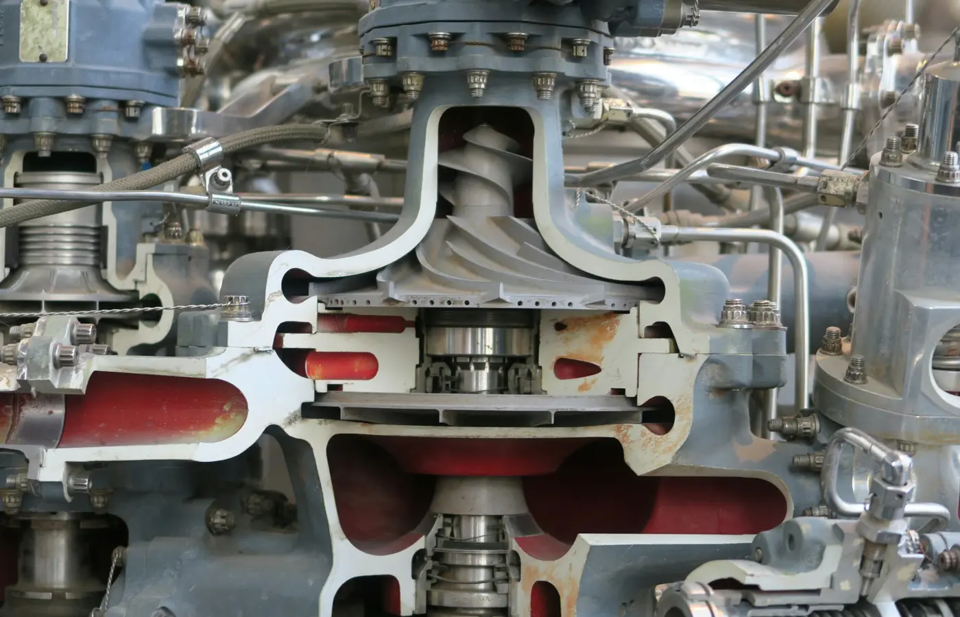
Mechanical seal selection is not a shaft-size exercise. The correct seal is determined by the environment at the seal faces: fluid composition and behavior, seal-chamber pressure and temperature, shaft movement, operating cycle, and the consequence of leakage. Face materials, secondary seals, arrangement, and flush or support system must work as one system. A seal that fits the pump dimensions can still fail early if its materials, face loading, or seal environment do not match the actual duty.
Define the seal-chamber duty before choosing a seal
Start with process data, pump data, and the conditions specifically at the seal chamber. Pump discharge pressure and bulk process temperature are useful inputs, but they may not fully describe the local conditions at the seal faces. Recirculation, heat generated at the faces, restricted flow paths, and vaporization can change the seal environment.
The Hydraulic Institute’s mechanical seal application guidance identifies selection, installation, operation, seal arrangements, and design classifications as separate subjects. That distinction is important: a technically sound seal selection can still be undermined by unsuitable piping, poor installation, or pump movement outside the seal’s stated limits.
Collect the following before comparing seal configurations or requesting quotations:
- Process-fluid name, composition, concentration, and safety data.
- Solids type, particle size where known, concentration, abrasiveness, and whether solids settle, crystallize, coke, or polymerize.
- Normal, startup, shutdown, cleaning, and upset temperatures at the seal chamber.
- Normal and maximum seal-chamber pressure, including dead-head, blocked-discharge, transient, and reverse-pressure cases where applicable.
- Fluid vapor pressure or boiling tendency at operating temperature, particularly for hot liquids, volatile fluids, and services near saturation.
- Pump speed, shaft or sleeve diameter, direction of rotation, and available seal-chamber dimensions.
- Shaft radial runout, axial movement, bearing condition, sleeve condition, and any known vibration issue.
- Operating pattern: continuous duty, standby service, frequent starts, dry-running exposure, thermal cycling, or intermittent flushing.
- Leakage consequences, including personnel exposure, fire risk, emissions requirements, drain routing, product contamination, and cleanup constraints.
Ask the pump OEM for the seal-chamber drawing and allowable shaft movement information rather than estimating these dimensions from an old seal sample. Ask the seal supplier for the application form for the exact proposed seal family. These forms are useful because they reveal which inputs affect that supplier’s rating; they do not replace a review of the actual duty.
A useful decision rule is simple: if fluid behavior, temperature, pressure, or shaft movement is uncertain, treat the selection as provisional. Resolve the missing input before releasing a purchase order, especially where leakage has a safety, environmental, or production consequence.
Match face, secondary-seal, and hardware materials to the fluid
A mechanical seal is a material system, not only a pair of rotating faces. The primary seal faces control leakage and heat generation. Secondary seals must retain elasticity or sealing function while moving or remaining static in their glands. Springs, retainers, drive components, and metal housings must withstand the fluid and external environment for the expected exposure period.
Select face pairs by lubrication, solids, and thermal behavior
Seal faces run with a very thin lubricating film between them during normal operation. Their suitability depends on how the process fluid lubricates, transfers heat, deposits solids, or flashes. A face combination appropriate for a clean, lubricating liquid may not tolerate abrasive slurry, poor-lubricity fluid, or intermittent vapor exposure in the same way.
Carbon-based faces are commonly used in many services because their friction and conformability characteristics can be useful in a lubricated seal interface. Hard faces such as silicon carbide or tungsten carbide are often considered where wear resistance, chemical resistance, or poor lubrication is a concern. These are broad material-selection principles, not universal compatibility rules. Grade, binder, impregnation, counterface, face geometry, pressure, and process contaminants can change the result.
For example, solids can damage faces through abrasion, while a liquid that crystallizes after a temperature change can obstruct springs, hang up secondary seals, or build deposits at the atmospheric side. A fluid that vaporizes in the seal chamber can reduce face lubrication and increase heat. These mechanisms should be reviewed against the supplier’s exact material recommendations and operating envelope.
Verify secondary seals and metal parts separately
Elastomer secondary seals are often supplied in materials such as FKM, EPDM, NBR, or perfluoroelastomer grades. PTFE-based secondary seals are also used in some designs. Do not select among them from a generic chemical-resistance chart alone. Check the exact compound or grade against fluid concentration, temperature, pressure, cleaning chemicals, exposure duration, and expected motion.
Compatibility must include more than the principal process fluid. Review solvents used for cleaning, additives, corrosion inhibitors, chloride-containing contamination where relevant, steam-out exposure, and any external washdown chemicals. A seal may encounter these fluids during startup, maintenance, or abnormal operation even when they are absent from the normal process stream.
Metal compatibility requires the same discipline. The wetted hardware material must be assessed for the process fluid, temperature, contaminants, and crevice conditions. The seal supplier should identify the actual metal grades in the bill of materials, rather than describing hardware only as “stainless steel.” If corrosion resistance is critical, include material traceability and any required documentation in the purchase specification.
Choose the seal design for pressure, temperature, and shaft movement
The design category affects how the seal responds to hydraulic loading, thermal distortion, secondary-seal movement, and installation variation. No design label alone establishes a pressure, temperature, speed, or movement limit. Confirm the manufacturer’s published limit for the exact configuration, face size, materials, gland, and support arrangement.
Balanced and unbalanced designs
A balanced seal reduces the hydraulic closing force acting on the faces relative to an unbalanced design. Lower closing force can reduce heat generation and improve the margin for higher seal-chamber pressure, volatile fluids, or services with limited lubricity. The PDH mechanical seal fundamentals document describes this general relationship, but its examples should not be used as ratings for another seal model.
An unbalanced seal may be suitable in lower-pressure duties where its simpler geometry and face loading are appropriate. The decision should follow actual chamber pressure, vaporization risk, fluid lubricity, and the proposed seal’s stated operating range. Selecting a balanced design does not remove the need to control temperature, maintain a suitable fluid environment, and prevent operation outside pump or seal limits.
Pusher and non-pusher seals
In a pusher seal, the secondary seal moves axially to compensate for face wear and shaft movement. In a non-pusher design, a metal bellows or another mechanism provides this movement without an elastomer sliding along the shaft or sleeve. The practical distinction is whether the service may cause the moving secondary seal to stick, wear, or be obstructed by deposits.
A pusher seal can be effective in many clean services, but deposits, corrosion products, or shaft-sleeve damage may interfere with secondary-seal movement. A non-pusher bellows design may be considered where eliminating a dynamic elastomer at the shaft is beneficial. Bellows material, fatigue limits, temperature capability, and pressure behavior still require review for the proposed model.
Cartridge, component, and spring configurations
Cartridge seals assemble the sealing components on a sleeve and gland with preset working length. This can reduce installation variables when installed according to the manufacturer’s instructions. It does not correct excessive shaft runout, worn bearings, damaged sleeves, incorrect gland alignment, or an unsuitable seal chamber.
Component seals can be appropriate where the pump design, repair practice, or application supports them, but their working length and installation dimensions require more direct control. Multiple-spring and single-spring designs also have different practical responses to solids, torque transmission, and available space. Select the design based on the process and equipment condition, not on a general assumption that one construction is more reliable.
Before installation, isolate electrical and process energy, depressurize and drain the pump as required by site procedures, and verify that the equipment is safe to work on. Check sleeve condition, runout, axial movement, gland face condition, and seal-chamber cleanliness against the pump OEM and seal manufacturer’s instructions. Refit guards before returning rotating equipment to service.
Select seal arrangement by leakage consequence
Seal arrangement is primarily a containment and support-system decision. It should reflect the consequences of process leakage, the ability of the fluid to lubricate the faces, emissions obligations, and the need to keep air, moisture, or an external fluid out of the process.
A single seal has one primary seal interface between the process and atmosphere. It may be appropriate where controlled leakage risk is acceptable and the fluid provides a manageable seal environment. A single seal can still require a flush, cooling, quench, drain connection, or other seal-environment control.
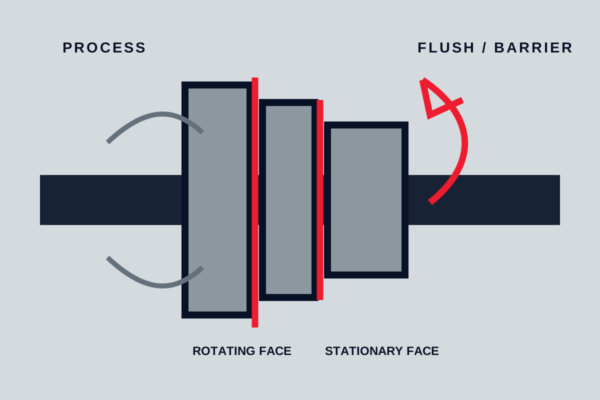
A dual unpressurized arrangement uses an inboard and outboard seal with buffer fluid between them. It can provide an additional containment stage and may support leakage monitoring. A dual pressurized arrangement uses barrier fluid maintained above process-side seal pressure so that the barrier fluid supports the inboard seal interface. This can reduce process-fluid leakage to atmosphere, but it introduces a separate support-system duty: barrier-fluid pressure, temperature, cleanliness, level, circulation, cooling, venting, instrumentation, and relief routing must all be controlled.
Do not assume that a dual seal automatically satisfies safety, emissions, or containment requirements. The complete system must be reviewed with process safety personnel, the pump OEM, and the seal-system supplier. The review should consider the hazard classification, support-fluid compatibility, pressure differential, alarm response, vent and drain destination, and the effect of a support-system failure.
Where an API plan number or arrangement terminology is proposed, confirm the current project-approved standard edition, equipment scope, and client specification. API-style terminology is useful for communicating a defined piping concept, but it is not automatically mandatory or suitable for every pump, industry, or fluid.
Specify a flush, quench, or barrier-fluid plan around the seal environment
A seal piping plan has a functional purpose. It may supply cleaner fluid, remove heat, control vaporization, exclude solids, prevent atmospheric-side deposits, or manage leakage. The appropriate plan follows the seal environment and arrangement rather than a default convention.
The John Crane piping plans pocket guide describes the general objective clearly: reliable sealing depends on creating a suitable fluid environment around the seal, while considering equipment, fluid properties, safety, and cost. Treat its plan illustrations as general reference material. Confirm routing, restrictions, instruments, and operating conditions with the selected seal and pump documentation.
Distinguish the fluid circuits
A process-fluid flush returns or introduces process fluid into the seal chamber. It can provide circulation or cooling, but it is only suitable if the fluid is clean enough, compatible with the seal materials, and available with sufficient pressure differential. A discharge recirculation plan, often identified as Plan 11 in applicable API terminology, should not be selected by default. Confirm the actual pressure differential, flow path, vaporization margin, process-fluid cleanliness, and restriction sizing with the manufacturer.
An external flush introduces a compatible external liquid to the seal chamber. It can improve the environment for some dirty or hot services, but it may dilute or contaminate the process. The process owner must decide whether that contamination is acceptable.
A quench is generally an atmospheric-side service intended to manage deposits, cool the outboard area, or limit exposure at the seal’s external side. It is not equivalent to a process-side flush and does not replace a dual-seal barrier-fluid system.
A buffer or barrier-fluid system serves a dual seal. Its design may include a reservoir, circulation device, cooler, pressure control, level indication, temperature indication, alarms, and a managed relief or vent path. The support fluid must be compatible with the seal materials and with the consequences of any leakage into the process or atmosphere.
For any proposed plan, verify:
- Fluid source, destination, and routing for normal and abnormal operation.
- Pressure differential at the actual seal connections, not only at a remote process instrument.
- Required cooling utility conditions, if a cooler is included.
- Fluid cleanliness and whether filters, cyclones, or other separation are necessary.
- Venting and drainage so trapped gas, flashing liquid, or accumulated leakage can be managed safely.
- Instrument ranges, alarm setpoints, response actions, and relief destination.
- Compatibility of all wetted support-system materials with the process and support fluid.
Turn the selection into a quote and acceptance checklist
A seal quotation based only on shaft diameter is incomplete. The buyer should be able to compare suppliers against a defined application datasheet and identify exclusions before order placement.
Request that the quotation states:
- Pump make and model, seal-chamber drawing reference, shaft or sleeve dimensions, rotation, and operating speed.
- Normal and maximum seal-chamber pressure and temperature, including relevant upset conditions.
- Fluid composition, solids information, vaporization concerns, and cleaning or flushing chemicals.
- Seal type, balance status, pusher or non-pusher construction, cartridge or component construction, and spring arrangement.
- Exact primary-face materials, secondary-seal compound or grade, wetted metal materials, and any special coatings.
- Single or dual arrangement, plus the complete proposed flush, quench, buffer, or barrier-fluid plan.
- Support-system components, instruments, connection sizes, tubing or piping scope, cooler duty assumptions, and pressure-relief routing requirements.
- Manufacturer operating limits for the quoted configuration, including stated pressure, temperature, speed, and shaft-movement constraints.
- General-arrangement drawing, bill of materials, installation instructions, recommended spares, and documentation requirements.
- Required material certificates, pressure tests, inspection points, witness requirements, and traceability obligations where specified by the project.
At receipt, compare the supplied seal and documentation with the approved drawing and purchase specification. Before commissioning, use the site procedure to confirm isolation removal, correct piping connections, fluid fill and venting, rotation check where safe and permitted, instrument readiness, guard reinstatement, and a controlled leak observation period. These actions must follow the equipment manufacturer’s instructions and site safety system.
The final selection rule is to specify the seal from the verified seal-chamber duty, then select materials, seal design, arrangement, and support plan as a matched package. If the service involves hazardous fluid, flashing conditions, uncertain chemical compatibility, significant solids, or a dual-seal support system, obtain a documented application review from the pump OEM and seal manufacturer before operation.